
How to Use LDO 3,3V: Examples, Pinouts, and Specs
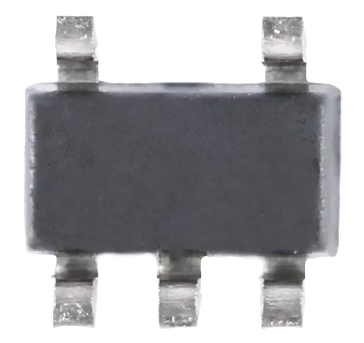
 Design with LDO 3,3V in Cirkit Designer
Introduction
A Low Dropout Regulator (LDO) is a type of voltage regulator designed to provide a stable and precise output voltage with minimal voltage drop between the input and output. The LDO 3.3V is specifically designed to deliver a constant 3.3V output, making it ideal for powering sensitive electronic circuits such as microcontrollers, sensors, and communication modules. Its low dropout voltage ensures efficient operation even when the input voltage is only slightly higher than the output voltage.
Explore Projects Built with LDO 3,3V
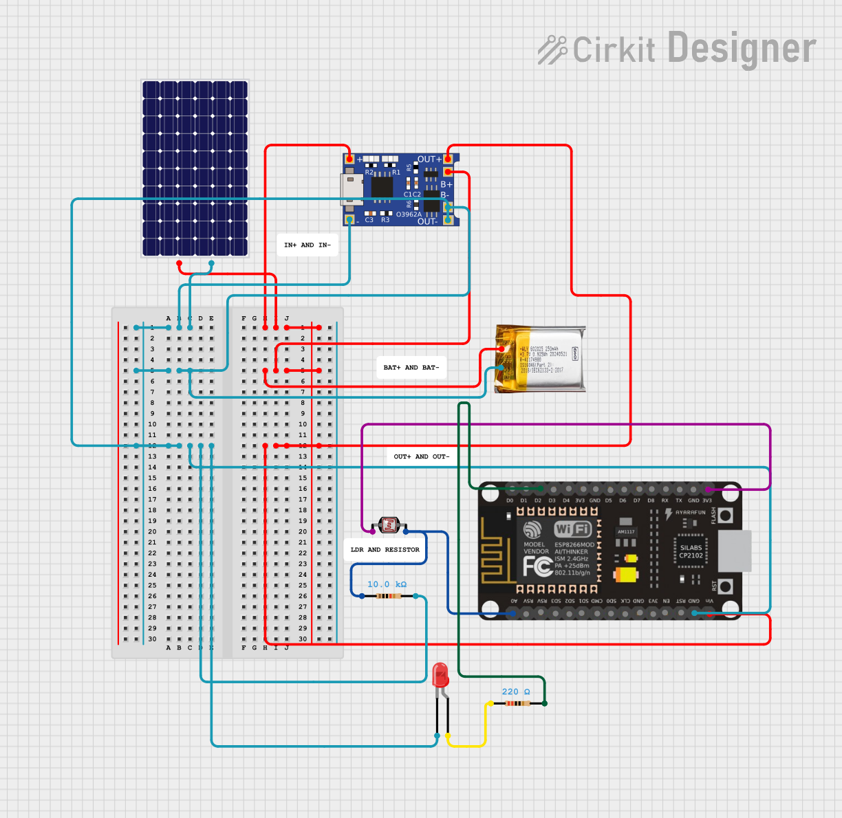 Open Project in Cirkit Designer
 Open Project in Cirkit Designer
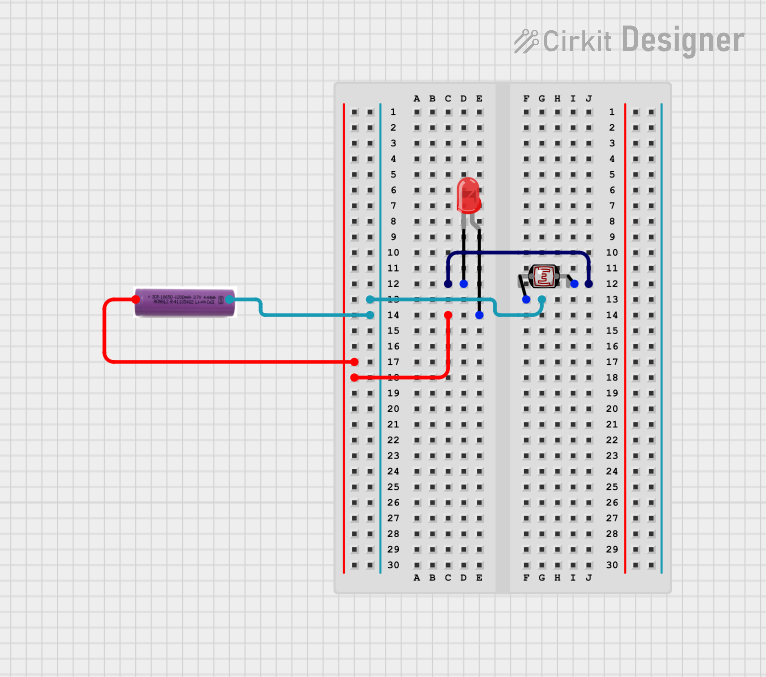 Open Project in Cirkit Designer
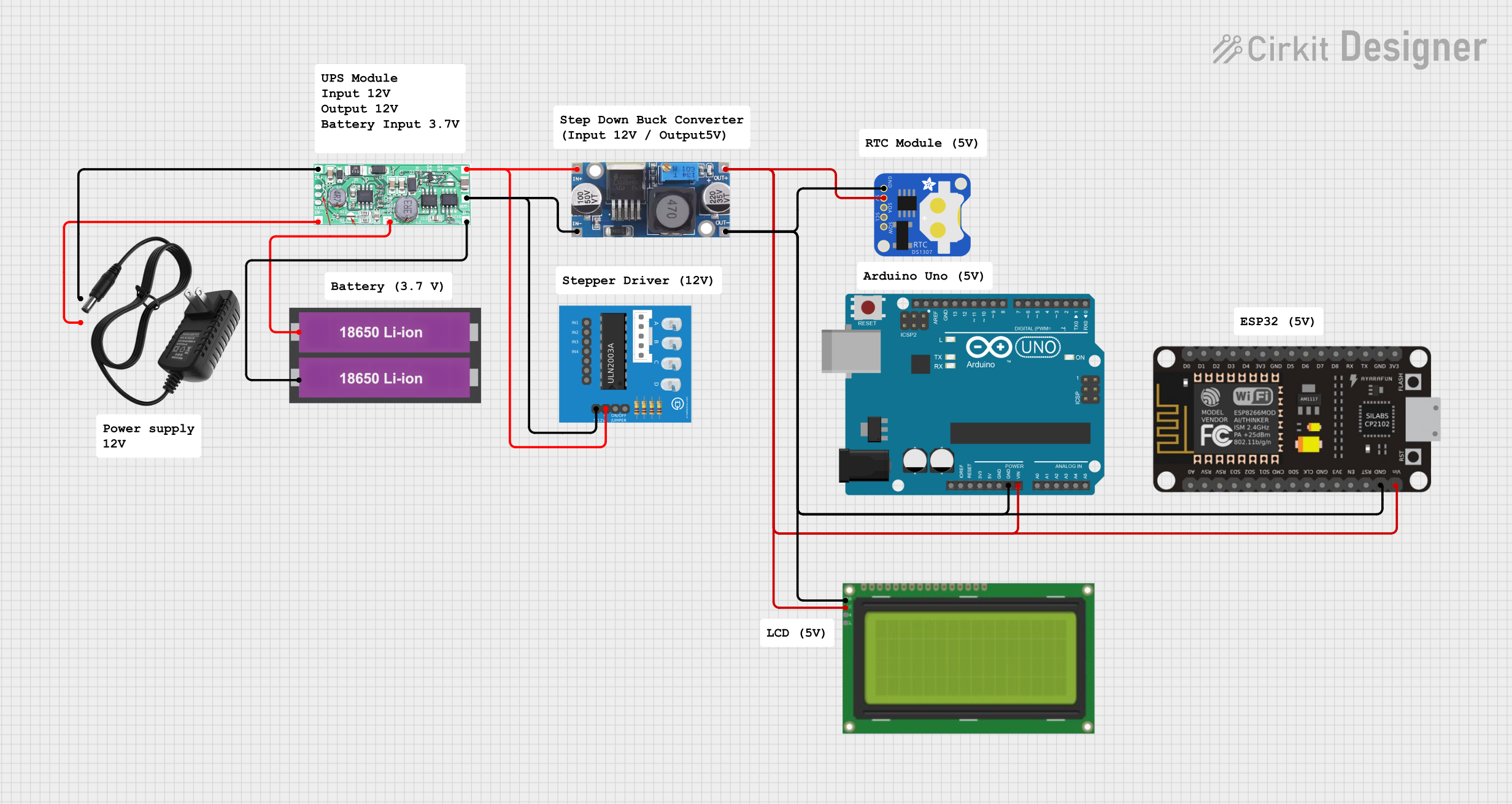 Open Project in Cirkit Designer
Explore Projects Built with LDO 3,3V
Open Project in Cirkit DesignerOpen Project in Cirkit DesignerOpen Project in Cirkit DesignerOpen Project in Cirkit DesignerCommon Applications
- Powering microcontrollers (e.g., Arduino, ESP32, STM32)
- Supplying stable voltage to sensors and analog circuits
- Battery-powered devices requiring low power consumption
- Noise-sensitive applications such as RF modules and audio circuits
Technical Specifications
The following table outlines the key technical details of the LDO 3.3V regulator:
| Parameter | Value |
|---|---|
| Output Voltage | 3.3V |
| Input Voltage Range | 3.5V to 12V |
| Dropout Voltage | Typically 0.2V to 0.5V (load-dependent) |
| Maximum Output Current | 500mA (varies by model) |
| Quiescent Current | Typically 1mA or less |
| Operating Temperature | -40°C to +125°C |
| Package Types | TO-220, SOT-223, SOT-23, etc. |
Pin Configuration
Below is the pin configuration for a common 3-pin LDO 3.3V regulator (e.g., in a TO-220 package):
| Pin Number | Pin Name | Description |
|---|---|---|
| 1 | Input (VIN) | Connect to the input voltage source |
| 2 | Ground (GND) | Connect to the circuit ground |
| 3 | Output (VOUT) | Provides the regulated 3.3V output |
Usage Instructions
How to Use the LDO 3.3V in a Circuit
- Input Voltage: Ensure the input voltage (VIN) is at least 0.5V higher than the desired output voltage (3.3V). For example, a 5V input is ideal for stable operation.
- Capacitors: Use appropriate input and output capacitors to ensure stability and reduce noise:
- Place a 10µF capacitor close to the input pin (VIN) to filter input voltage fluctuations.
- Place a 10µF capacitor close to the output pin (VOUT) to stabilize the output voltage.
- Connections:
- Connect the input voltage source to the VIN pin.
- Connect the GND pin to the circuit ground.
- Connect the VOUT pin to the load requiring 3.3V.
Example Circuit
Below is a simple circuit diagram for using the LDO 3.3V:
Input Voltage (e.g., 5V) ----[10µF Capacitor]---- VIN (Pin 1)
                                |
                               GND (Pin 2) ---- Circuit Ground
                                |
Output Voltage (3.3V) ----[10µF Capacitor]---- VOUT (Pin 3)
Using with Arduino UNO
The LDO 3.3V can be used to power an Arduino UNO or provide a stable 3.3V supply for sensors connected to the Arduino. Below is an example code snippet for reading a sensor powered by the LDO 3.3V:
// Example: Reading an analog sensor powered by the LDO 3.3V
const int sensorPin = A0; // Sensor connected to analog pin A0
int sensorValue = 0;      // Variable to store sensor reading

void setup() {
  Serial.begin(9600); // Initialize serial communication
}

void loop() {
  sensorValue = analogRead(sensorPin); // Read the sensor value
  Serial.print("Sensor Value: ");
  Serial.println(sensorValue); // Print the sensor value to the Serial Monitor
  delay(500); // Wait for 500ms before the next reading
}
Important Considerations
- Thermal Management: If the LDO is dissipating significant power (e.g., high input voltage and high current), use a heatsink or ensure proper ventilation to prevent overheating.
- Load Current: Ensure the load current does not exceed the maximum output current rating of the LDO.
- Input Voltage: Avoid input voltages below the minimum required for proper regulation, as this can cause unstable output.
Troubleshooting and FAQs
Common Issues and Solutions
Output Voltage is Incorrect or Unstable:
- Check the input voltage to ensure it is within the specified range and at least 0.5V higher than the output voltage.
- Verify that the input and output capacitors are properly connected and have the correct values.
- Ensure the load current does not exceed the maximum rating of the LDO.
LDO Overheating:
- Check for excessive power dissipation (Power = (VIN - VOUT) × Load Current).
- Use a heatsink or reduce the input voltage if possible.
- Ensure proper airflow around the LDO.
No Output Voltage:
- Verify all connections, especially the VIN and GND pins.
- Check for short circuits or damaged components in the circuit.
FAQs
Q: Can I use the LDO 3.3V with a 3.3V input voltage?
A: No, the input voltage must be at least 0.5V higher than the output voltage for proper regulation. Use a higher input voltage, such as 5V.
Q: What happens if I don't use capacitors with the LDO?
A: Without capacitors, the LDO may become unstable, leading to output voltage fluctuations or oscillations. Always use the recommended capacitor values.
Q: Can the LDO power multiple devices simultaneously?
A: Yes, as long as the total current drawn by all devices does not exceed the maximum output current rating of the LDO.
Q: How do I calculate power dissipation in the LDO?
A: Power dissipation is calculated as (VIN - VOUT) × Load Current. Ensure the LDO can handle the calculated power dissipation without overheating.