How to Use LCM1602 IIC: Examples, Pinouts, and Specs
Introduction
The LCM1602 IIC is a 16x2 character LCD module that provides a simple and cost-effective solution for adding a small visual interface to your electronics projects. This module is capable of displaying two lines of text, with up to 16 characters per line. It utilizes the I2C communication protocol, which minimizes the number of pins required for operation, making it ideal for use with microcontrollers with limited GPIO pins, such as the Arduino UNO.
Explore Projects Built with LCM1602 IIC
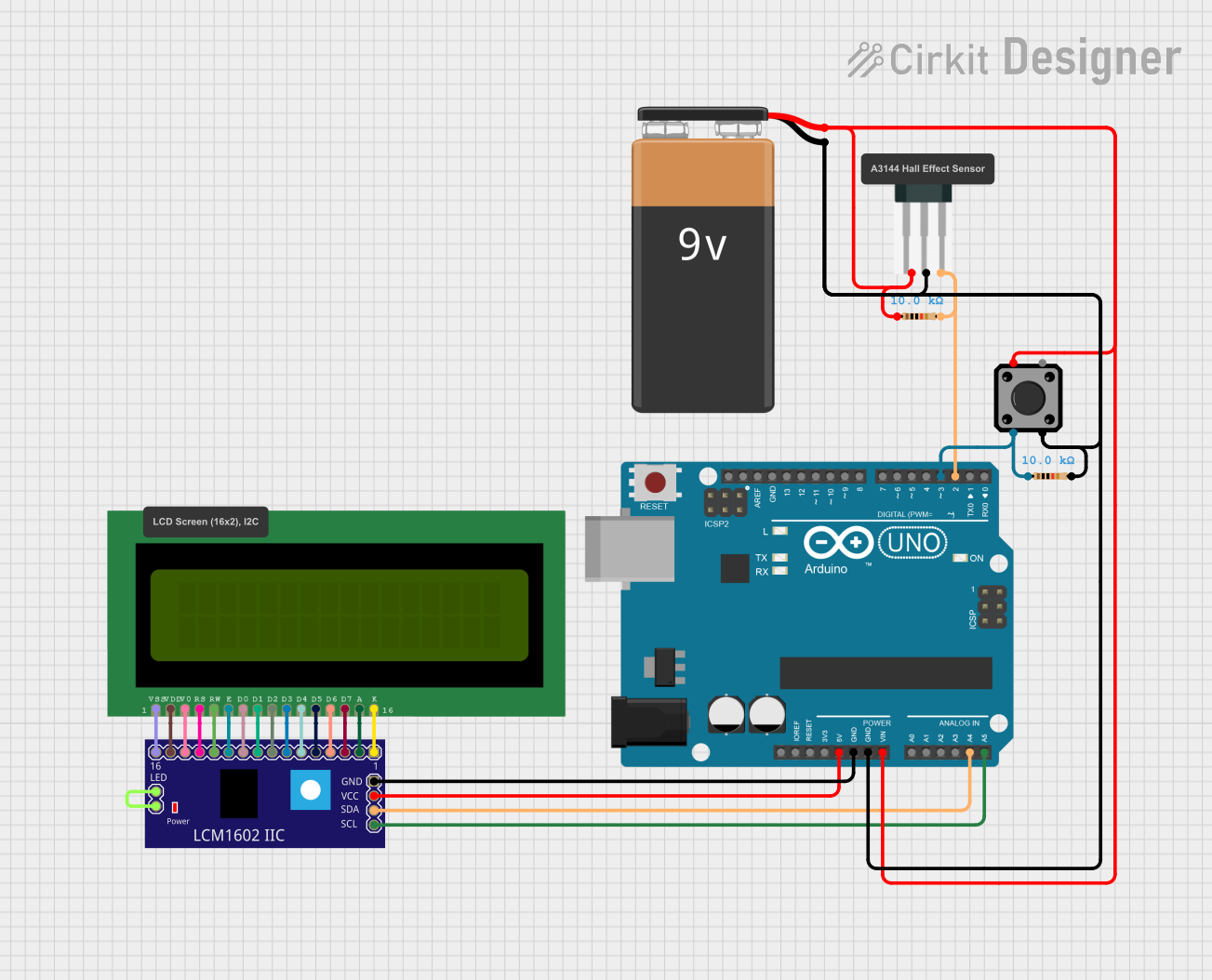
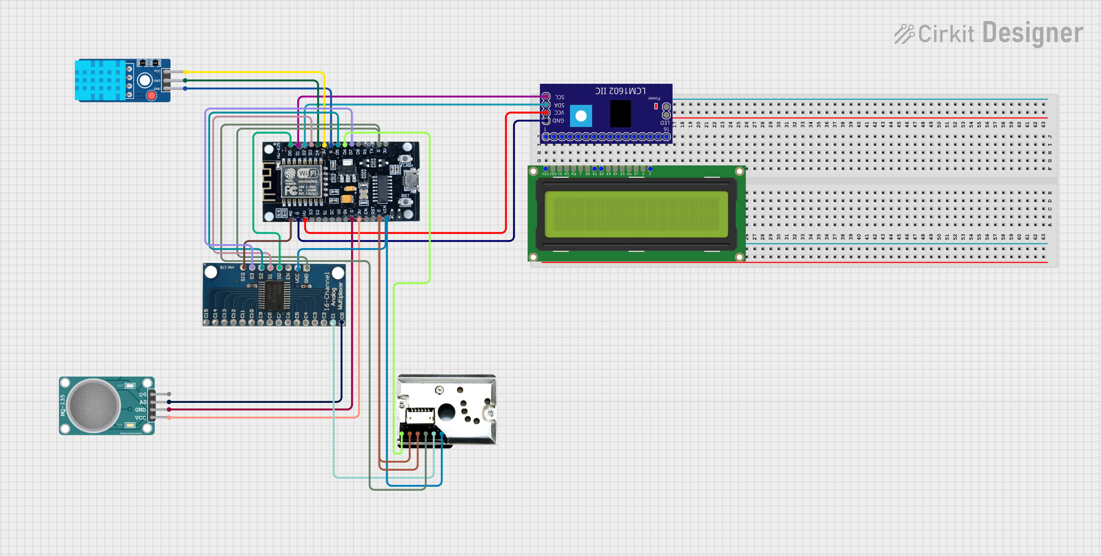
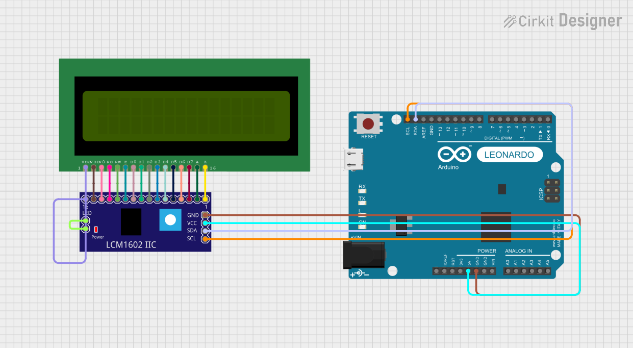

Explore Projects Built with LCM1602 IIC
Common Applications and Use Cases
- User interfaces for small-scale projects
- Displaying sensor readings
- Showing status messages and menus
- Prototyping and educational purposes
Technical Specifications
Key Technical Details
- Display: 16 characters x 2 lines
- Character Size: 5 x 8 pixels
- Backlight: LED, Yellow-Green
- Communication: I2C interface
- Supply Voltage: 5V
- I2C Address: 0x27 (default, can vary)
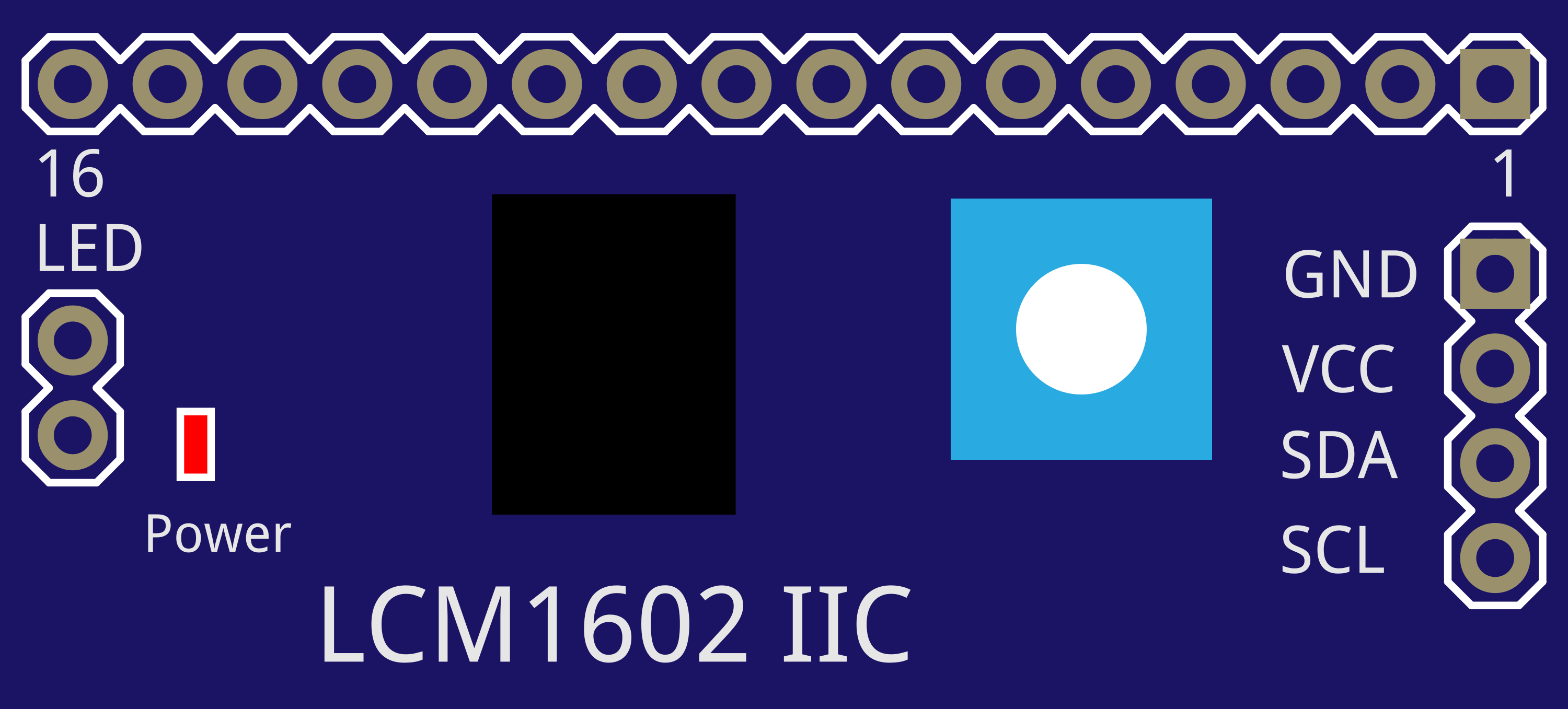
Pin Configuration and Descriptions
| Pin | Description |
|---|---|
| GND | Ground |
| VCC | 5V Power Supply |
| SDA | I2C Data Line |
| SCL | I2C Clock Line |
| LED | Backlight Anode (5V) |
Usage Instructions
How to Use the Component in a Circuit
- Connect the GND pin to the ground of your power supply.
- Connect the VCC pin to a 5V supply.
- Connect the SDA and SCL pins to the I2C data and clock lines on your microcontroller.
- Optionally, connect the LED pin to 5V through a current-limiting resistor to turn on the backlight.
Important Considerations and Best Practices
- Ensure that pull-up resistors are connected to the SDA and SCL lines if your microcontroller does not have built-in pull-ups.
- Avoid long I2C cable runs to prevent signal degradation.
- Use a level shifter if you're interfacing with a microcontroller that operates at a logic level other than 5V.
Example Code for Arduino UNO
#include <Wire.h>
#include <LiquidCrystal_I2C.h>

// Initialize the library with the I2C address (0x27 for the LCM1602 IIC)
LiquidCrystal_I2C lcd(0x27, 16, 2);

void setup() {
  // Initialize the LCD
  lcd.init();
  // Turn on the backlight
  lcd.backlight();
  // Print a message to the LCD
  lcd.setCursor(0, 0);
  lcd.print("Hello, World!");
}

void loop() {
  // Main loop code (if required)
}
Troubleshooting and FAQs
Common Issues Users Might Face
- Display not powering on: Check the connections to VCC and GND, and ensure that the power supply is at 5V.
- Characters not displaying correctly: Verify that the I2C address is correct and that the SDA and SCL lines are properly connected.
- Backlight not working: Ensure that the LED pin is connected to 5V, possibly through a resistor.
Solutions and Tips for Troubleshooting
- Use an I2C scanner sketch to confirm the I2C address of the LCD module.
- Check for soldering issues on the I2C module pins.
- Adjust the contrast potentiometer on the back of the LCD module if characters are faint or too dark.
FAQs
Q: How do I change the I2C address of the module? A: The I2C address can be changed by adjusting the hardware on the I2C interface module, often by changing solder jumpers or DIP switches.
Q: Can I use this module with a 3.3V system? A: While the module is designed for 5V, some users have successfully operated it at 3.3V. However, for reliable operation, a level shifter is recommended.
Q: Is it possible to turn off the backlight to save power? A: Yes, you can turn off the backlight by disconnecting the LED pin or controlling it via a digital pin on your microcontroller.
This documentation provides a comprehensive guide to using the LCM1602 IIC LCD module. For further assistance, consult the datasheet or contact technical support.