How to Use RC Receiver Module: Examples, Pinouts, and Specs
Introduction
An RC (Radio Control) Receiver Module is an essential component in remote control systems. It is designed to receive radio signals transmitted by an RC transmitter and convert them into electrical signals that can be used to control various functions of a remote-controlled device, such as a car, boat, drone, or airplane. These modules are widely used in hobbyist projects, robotics, and in the development of autonomous systems.
Explore Projects Built with RC Receiver Module


Explore Projects Built with RC Receiver Module
Common Applications and Use Cases
- Remote-controlled vehicles (cars, boats, planes)
- Drones and quadcopters
- DIY robotics projects
- Home automation systems
- Wireless control systems
Technical Specifications
Key Technical Details
- Operating Voltage: Typically 4.8V to 6V
- Operating Frequency: Commonly 2.4 GHz (varies by region and standard)
- Channels: Number of control channels can vary (e.g., 4, 6, 8 channels)
- Modulation: Often uses PWM (Pulse Width Modulation) for signal encoding
- Range: Varies with transmitter power and environmental conditions
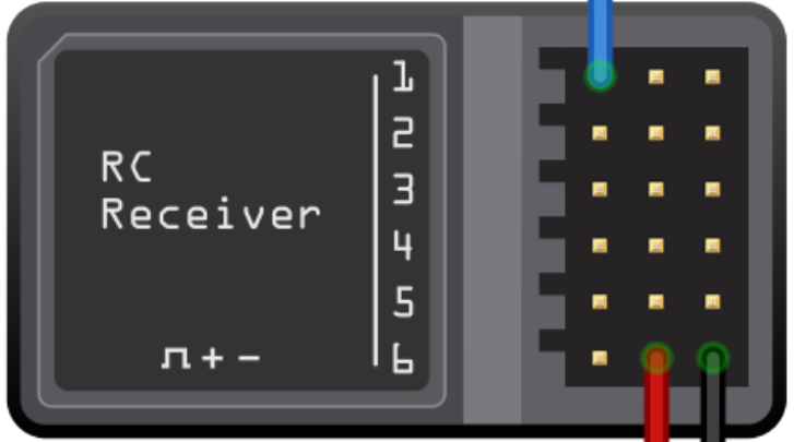
Pin Configuration and Descriptions
| Pin Number | Description | Notes |
|---|---|---|
| 1 | Ground (GND) | Connect to system ground |
| 2 | Power (VCC) | Typically 4.8V to 6V |
| 3-n | Channel Outputs (CH1, CH2...) | PWM signal outputs for each channel |
| n+1 | Battery Input (BAT) | Optional, for direct battery input |
| n+2 | Bind (BIND) | Used for pairing with a transmitter |
Usage Instructions
How to Use the Component in a Circuit
- Power Connection: Connect the VCC pin to a suitable power supply within the specified voltage range and the GND pin to the system ground.
- Channel Outputs: Connect each channel output to the corresponding control input of the device you wish to control (e.g., servos, ESCs).
- Binding: Follow the manufacturer's instructions to bind the receiver to your specific transmitter model. This usually involves pressing the BIND button while powering on the receiver.
- Testing: Verify the operation of each channel by observing the response of the connected devices when the corresponding controls are manipulated on the transmitter.
Important Considerations and Best Practices
- Ensure that the power supply is clean and within the specified voltage range to avoid damaging the receiver.
- Place the receiver away from metal objects and electronic interference to maximize signal quality.
- Antenna placement is crucial for optimal reception; avoid coiling or cutting the antenna.
- For safety, perform initial tests in a controlled environment to prevent accidents.
Troubleshooting and FAQs
Common Issues Users Might Face
- No Response from Receiver: Ensure that the receiver is properly powered and bound to the transmitter. Check the antenna and the distance between the transmitter and receiver.
- Intermittent Control: This could be due to low battery power, interference, or obstacles blocking the signal. Check the battery levels and the environment for potential sources of interference.
- Limited Range: If the control range is less than expected, ensure that the antenna is properly positioned and not damaged. Also, check for environmental factors that could be limiting the range.
Solutions and Tips for Troubleshooting
- Always perform a range check before using the RC system to ensure proper operation.
- If the receiver is not responding, try re-binding it to the transmitter.
- Inspect the wiring connections to ensure they are secure and not causing intermittent issues.
FAQs
- Q: Can I use any transmitter with my RC receiver?
- A: The transmitter and receiver must be compatible, typically from the same manufacturer and using the same frequency and modulation scheme.
- Q: How many devices can I control with my RC receiver?
- A: This depends on the number of channels your receiver has. Each channel can typically control one device or function.
Example Code for Arduino UNO
Below is an example of how to read PWM signals from an RC Receiver using an Arduino UNO:
#include <Servo.h>

Servo myServo; // Create servo object to control a servo

// This pin must be an interrupt-capable pin
const int receiverPin = 2;

volatile int pulseLength;

void setup() {
  myServo.attach(9); // Attaches the servo on pin 9 to the servo object
  pinMode(receiverPin, INPUT);
  attachInterrupt(digitalPinToInterrupt(receiverPin), pulseWidth, CHANGE);
}

void loop() {
  int servoPosition = map(pulseLength, 1000, 2000, 0, 180);
  myServo.write(servoPosition);
}

void pulseWidth() {
  if (digitalRead(receiverPin) == HIGH) {
    // Record the start time of the pulse
    pulseLength = micros();
  } else {
    // Calculate the pulse length
    pulseLength = micros() - pulseLength;
  }
}
Note: The pulseWidth function is an interrupt service routine (ISR) that measures the width of the incoming PWM pulses. The map function is then used to convert this pulse width into a servo position.
Remember to adjust the map function parameters (1000, 2000, 0, 180) to match the specific pulse width range of your RC receiver and the angle range of your servo.