How to Use Resettable Fuse PTC: Examples, Pinouts, and Specs
Introduction
A Resettable Fuse PTC (Positive Temperature Coefficient) is an electronic component designed to provide overcurrent protection in electrical circuits. Unlike traditional fuses, which must be replaced after a single use, resettable fuses can return to their normal state after the overcurrent condition is removed, allowing them to be used multiple times. They are commonly used in a variety of applications, including consumer electronics, automotive circuits, and battery packs, to prevent damage from overcurrent conditions.
Explore Projects Built with Resettable Fuse PTC


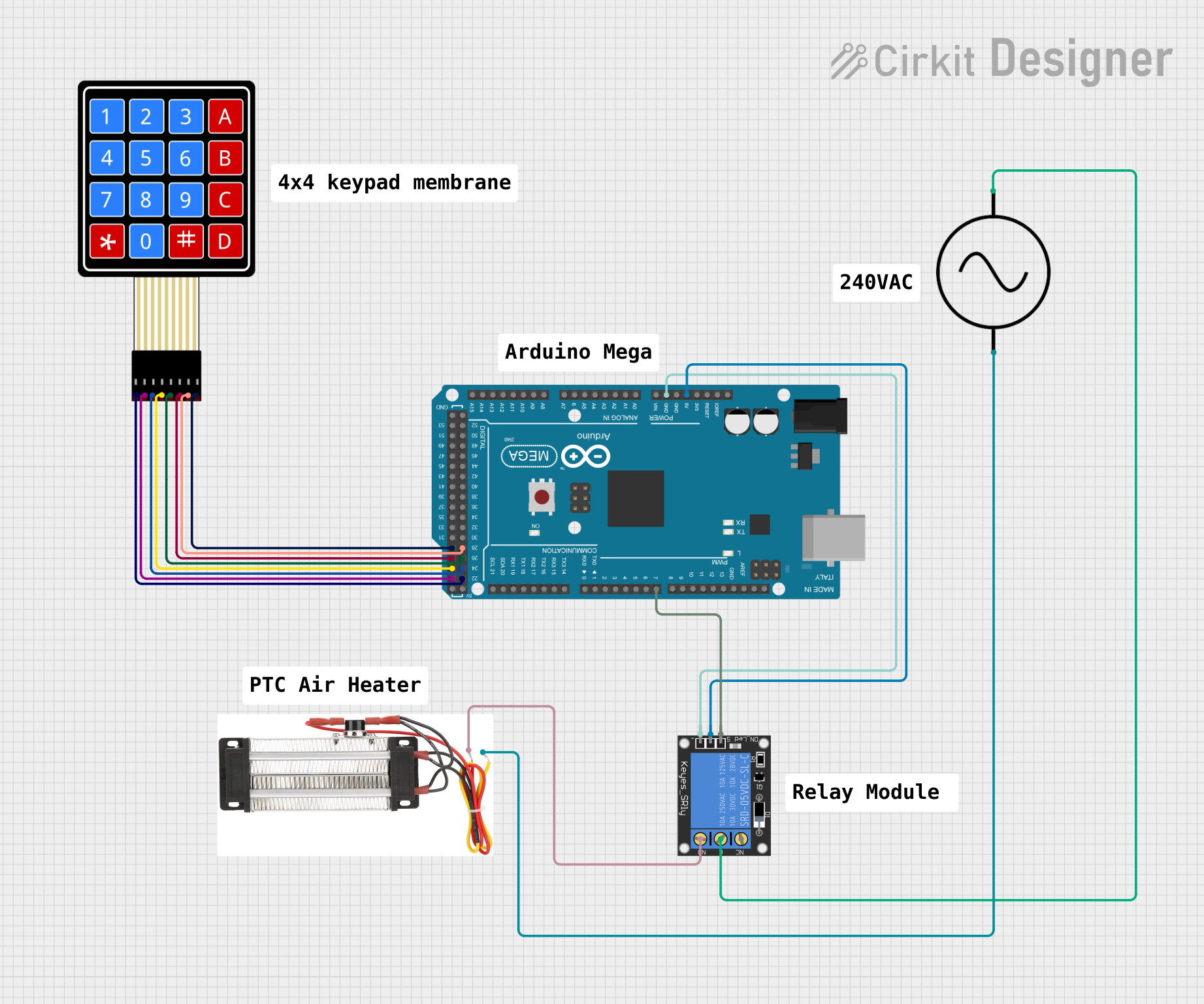
Explore Projects Built with Resettable Fuse PTC
Technical Specifications
Key Technical Details
| Parameter | Value Range | Description |
|---|---|---|
| Operating Voltage | X - Y VDC | The voltage range the PTC can handle. |
| Hold Current (Ih) | A - B mA | The maximum current before tripping. |
| Trip Current (It) | C - D mA | The current at which the PTC will trip. |
| Maximum Interrupt | E A | The maximum current the PTC can interrupt. |
| Time to Trip | F - G ms | The time it takes to trip at It. |
| Resistance | H - I Ohms | The resistance after tripping. |
| Reset Time | J - K seconds | The time it takes to reset after cooling. |
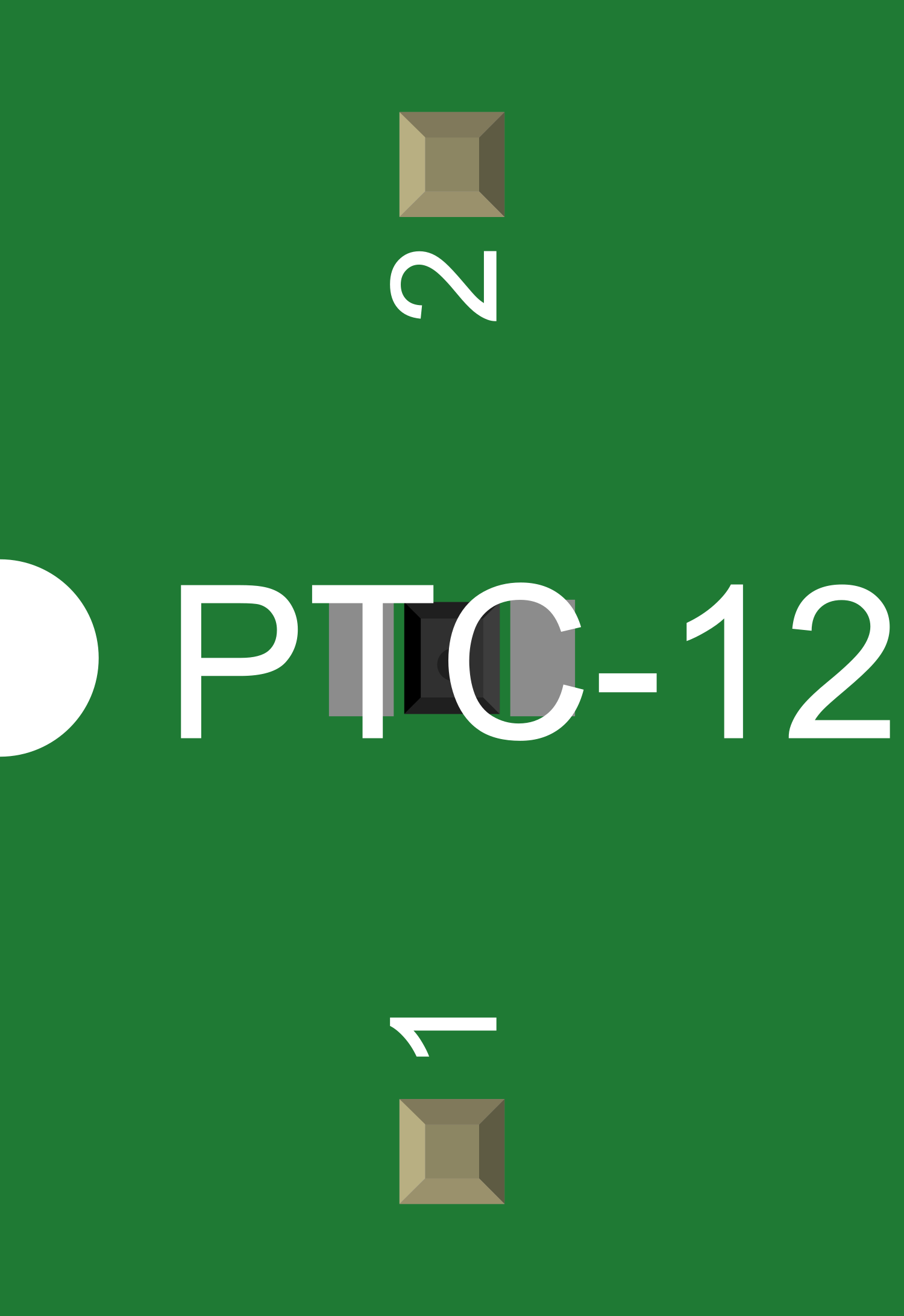
Pin Configuration and Descriptions
| Pin Number | Description |
|---|---|
| 1 | Current Input |
| 2 | Current Output |
Note: The values X, Y, A, B, C, D, E, F, G, H, I, J, and K should be replaced with the actual specifications of the PTC being documented.
Usage Instructions
How to Use the Component in a Circuit
- Circuit Integration: Place the PTC in series with the load that requires overcurrent protection.
- Voltage Consideration: Ensure the operating voltage of the circuit does not exceed the PTC's rated voltage.
- Current Rating: Select a PTC with a hold current rating slightly above the normal operating current of the circuit.
- Mounting: If applicable, mount the PTC to a surface that allows for heat dissipation.
Important Considerations and Best Practices
- Temperature Sensitivity: Be aware that ambient temperature can affect the PTC's trip current.
- Recovery Time: Allow time for the PTC to cool down and reset after an overcurrent event.
- Testing: Regularly test the PTC to ensure it is functioning correctly.
- Supplementary Protection: Consider using the PTC in conjunction with other protective devices for enhanced safety.
Troubleshooting and FAQs
Common Issues
- PTC Does Not Reset: Ensure the overcurrent condition has been removed and sufficient cooling time has passed.
- False Tripping: Verify that the selected PTC's hold current is appropriate for the circuit's normal operating current.
Solutions and Tips for Troubleshooting
- Check Connections: Loose connections can cause intermittent tripping. Ensure all connections are secure.
- Ambient Temperature: If the PTC is in a high-temperature environment, it may trip prematurely. Consider a PTC with a higher trip current or improve cooling.
FAQs
Q: Can a PTC be used multiple times? A: Yes, a PTC is designed to reset itself after an overcurrent condition is removed and it cools down.
Q: How quickly does a PTC respond to overcurrent conditions? A: Response times vary but are typically in the milliseconds range, depending on the specific PTC and the severity of the overcurrent.
Q: What happens if a PTC is subjected to an overcurrent beyond its maximum interrupt rating? A: The PTC may not be able to protect the circuit and could become damaged, failing to reset.
Example Code for Arduino UNO
// Example code to demonstrate the use of a PTC with an Arduino UNO
// This code assumes a PTC is placed in series with a load connected to pin 13

void setup() {
  pinMode(13, OUTPUT); // Set the digital pin as output
}

void loop() {
  digitalWrite(13, HIGH); // Turn on the load
  delay(1000);            // Wait for 1 second
  digitalWrite(13, LOW);  // Turn off the load
  delay(1000);            // Wait for 1 second
}

// Note: This code does not directly interact with the PTC.
// The PTC's function is independent of the microcontroller and will
// protect the circuit in case of an overcurrent situation.
Note: The example code provided is a basic illustration of how a load might be controlled with an Arduino. The PTC's operation is passive and does not require software control to provide protection.