How to Use Qduino Mini: Examples, Pinouts, and Specs
Introduction
The Qduino Mini is a miniaturized Arduino-compatible microcontroller board designed by Qtechknow. It is specifically tailored for projects with space constraints without compromising on the functionality and power of a standard Arduino board. The Qduino Mini is notable for its built-in battery charger and fuel gauge, which makes it an excellent choice for portable and wearable electronics.
Explore Projects Built with Qduino Mini

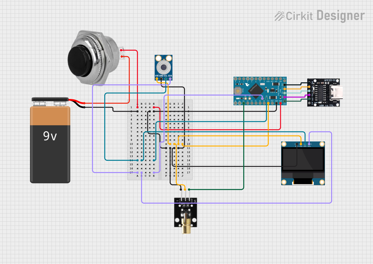
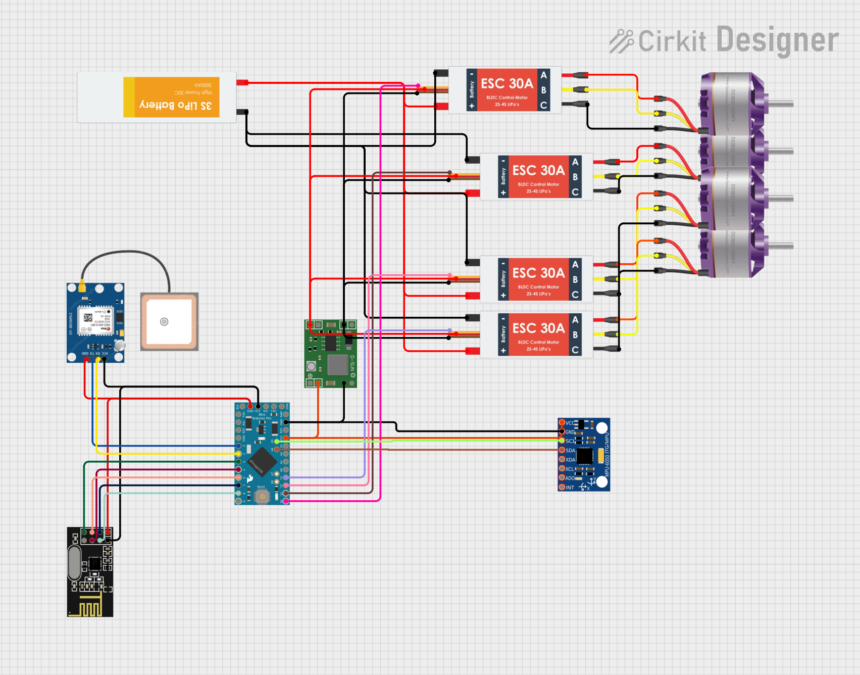
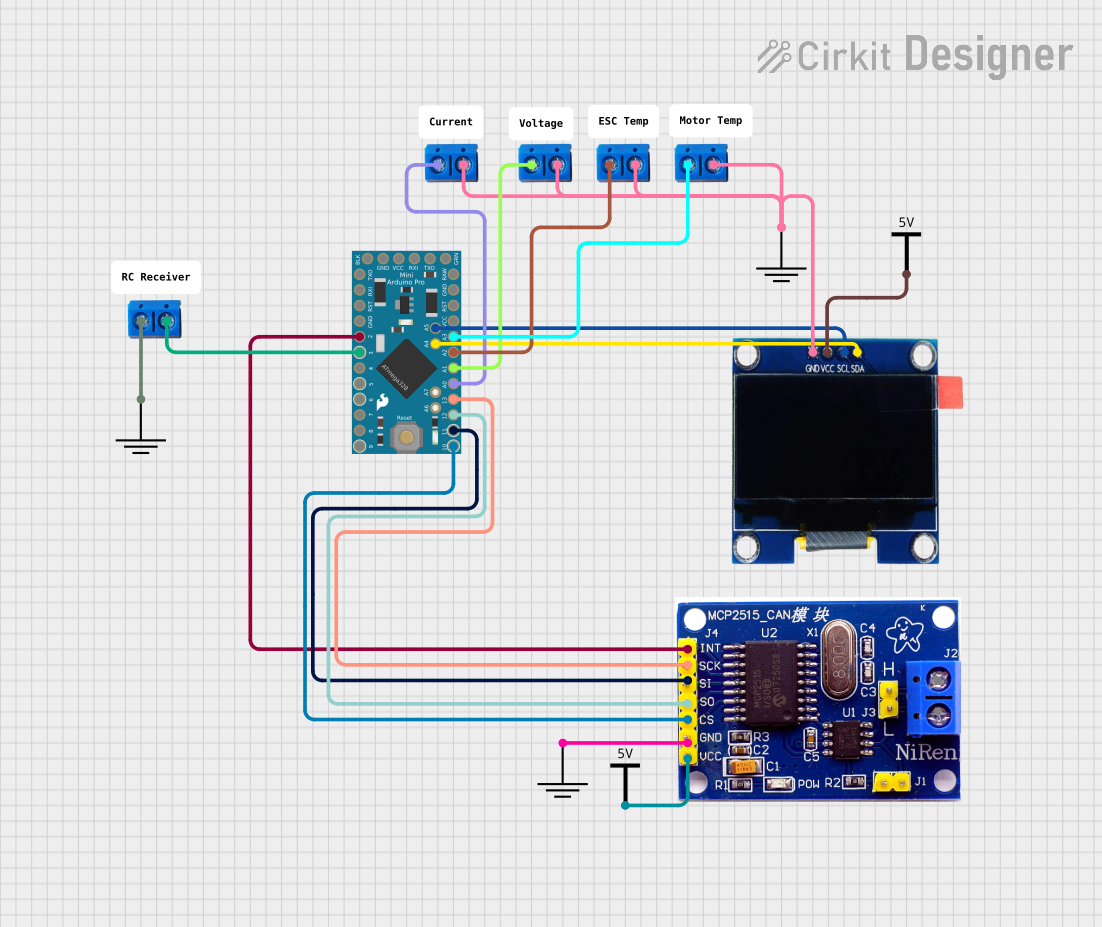
Explore Projects Built with Qduino Mini
Common Applications and Use Cases
- Wearable devices
- Portable electronics
- Prototyping small-scale projects
- Educational purposes for learning electronics and programming
- IoT devices with size restrictions
Technical Specifications
Key Technical Details
- Microcontroller: ATmega32U4
- Operating Voltage: 5V
- Input Voltage (recommended): 3.7V LiPo battery or 5V via USB
- Digital I/O Pins: 20
- PWM Channels: 7
- Analog Input Channels: 12
- DC Current per I/O Pin: 40 mA
- Flash Memory: 32 KB (ATmega32U4) of which 4 KB used by bootloader
- SRAM: 2.5 KB (ATmega32U4)
- EEPROM: 1 KB (ATmega32U4)
- Clock Speed: 16 MHz
- Built-in battery charging and fuel gauge
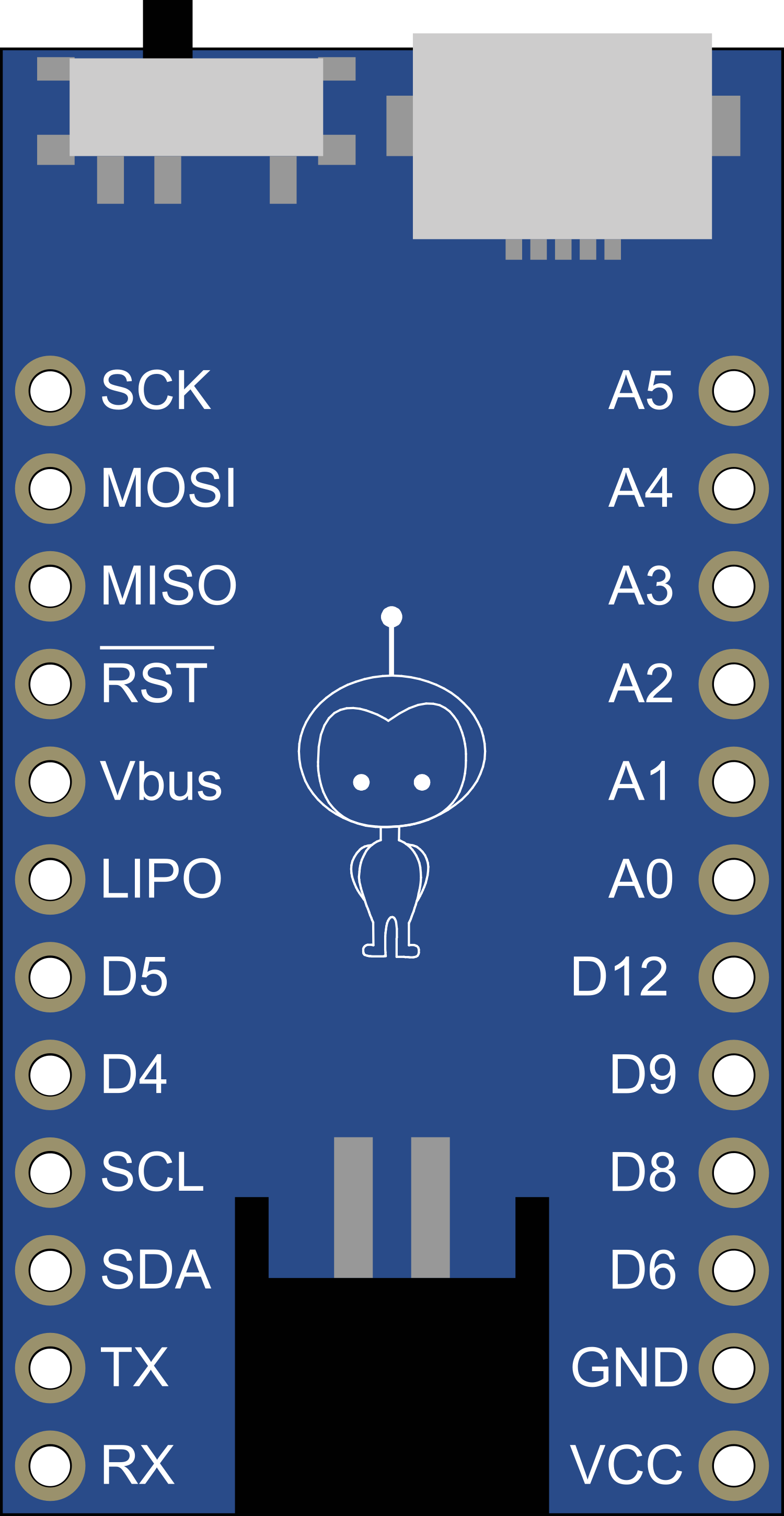
Pin Configuration and Descriptions
| Pin Number | Function | Description |
|---|---|---|
| 1 | TXD | Serial transmission |
| 2 | RXD | Serial reception |
| 3-8 | Digital I/O | General purpose digital input/output pins |
| 9-10 | PWM | Pulse Width Modulation output |
| 11-16 | Digital I/O | General purpose digital input/output pins |
| 17 | AREF | Analog reference voltage |
| 18-23 | Analog In | Analog input channels |
| 24 | GND | Ground |
| 25 | RESET | Reset pin |
| 26 | 3V3 | 3.3V output |
| 27 | 5V | 5V output |
| 28 | GND | Ground |
| 29 | VIN | Battery input voltage |
Usage Instructions
How to Use the Qduino Mini in a Circuit
Powering the Qduino Mini:
- Connect a 3.7V LiPo battery to the battery connector for portable applications.
- Alternatively, power the Qduino Mini through the USB port using a 5V USB power source.
Programming the Qduino Mini:
- Connect the Qduino Mini to a computer using a micro USB cable.
- Select "Arduino Leonardo" from the Board menu in the Arduino IDE, as the Qduino Mini uses the same ATmega32U4 processor.
Connecting I/O Devices:
- Use the digital and analog pins to connect sensors, actuators, and other components.
- Ensure that the connected devices are compatible with the operating voltage and current limitations of the Qduino Mini.
Important Considerations and Best Practices
- Always disconnect the battery when programming the Qduino Mini to prevent power conflicts.
- Do not exceed the recommended voltage and current specifications to avoid damaging the board.
- Use the onboard LED indicators to monitor battery charging and status.
- Utilize the fuel gauge to keep track of battery life in your portable projects.
Troubleshooting and FAQs
Common Issues Users Might Face
Qduino Mini not recognized by the computer:
- Ensure the micro USB cable is properly connected and functioning.
- Check that the correct drivers are installed for the ATmega32U4 processor.
Battery not charging:
- Verify that the battery is properly connected to the Qduino Mini.
- Check the battery with an external charger to ensure it is not defective.
Inconsistent behavior or crashes:
- Ensure that the power supply is stable and within the recommended voltage range.
- Check for any shorts or incorrect connections in the circuit.
Solutions and Tips for Troubleshooting
- Always start by checking connections and ensuring that the board is powered correctly.
- Use the Arduino IDE's Serial Monitor to debug and print out messages from the Qduino Mini.
- If the board is unresponsive, try resetting it using the onboard RESET button.
Example Code for Arduino UNO
// Blink the onboard LED
void setup() {
  pinMode(13, OUTPUT); // Set the LED pin as an output
}

void loop() {
  digitalWrite(13, HIGH);   // Turn the LED on
  delay(1000);              // Wait for a second
  digitalWrite(13, LOW);    // Turn the LED off
  delay(1000);              // Wait for a second
}
Note: The example code provided is for the Arduino UNO but is also compatible with the Qduino Mini since they share similar programming architecture. Ensure to select the correct board ("Arduino Leonardo") in the Arduino IDE when uploading the code to the Qduino Mini.