How to Use 5V Relay Module: Examples, Pinouts, and Specs
Introduction
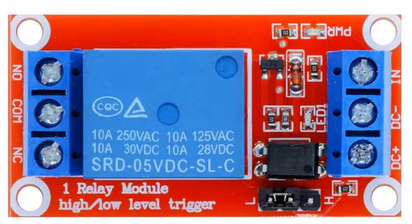
A 5V Relay Module is an electronic switch that allows a low voltage control signal to switch a higher voltage circuit. It typically consists of a relay, which is an electromechanical switch, and additional components to interface with microcontrollers or other control systems. This module is commonly used in automation projects to control devices like lights, motors, and other appliances.
Explore Projects Built with 5V Relay Module


Explore Projects Built with 5V Relay Module
Common Applications and Use Cases
- Home automation systems
- Industrial automation
- Remote control of appliances
- Motor control in robotics
- Switching high voltage devices with low voltage signals
Technical Specifications
Key Technical Details
| Specification | Value |
|---|---|
| Operating Voltage | 5V DC |
| Relay Type | Electromechanical |
| Maximum Load Voltage | 250V AC / 30V DC |
| Maximum Load Current | 10A |
| Control Signal | 5V TTL |
| Isolation | Opto-isolated |
Pin Configuration and Descriptions
| Pin Number | Pin Name | Description |
|---|---|---|
| 1 | IN | Control signal input (5V TTL) |
| 2 | GND | Ground connection |
| 3 | VCC | Power supply (5V) |
| 4 | NO | Normally Open contact (output) |
| 5 | NC | Normally Closed contact (output) |
| 6 | COM | Common contact (output) |
Usage Instructions
How to Use the Component in a Circuit
Wiring the Relay Module:
- Connect the VCC pin to the 5V power supply.
- Connect the GND pin to the ground of the power supply.
- Connect the IN pin to a digital output pin of your microcontroller (e.g., Arduino).
- Connect the device you want to control to the NO or NC and COM pins, depending on your application.
Controlling the Relay:
- To turn on the relay, send a HIGH signal (5V) to the IN pin.
- To turn off the relay, send a LOW signal (0V) to the IN pin.
Important Considerations and Best Practices
- Ensure that the relay's load specifications are not exceeded to prevent damage.
- Use appropriate flyback diodes if controlling inductive loads to protect the circuit.
- Always isolate high voltage circuits from low voltage control circuits to ensure safety.
- Use proper heat dissipation methods if the relay is used for extended periods.
Troubleshooting and FAQs
Common Issues Users Might Face
Relay Not Activating:
- Check the control signal voltage at the IN pin.
- Ensure the power supply is connected correctly.
Relay Sticking:
- Verify that the load does not exceed the relay's ratings.
- Check for mechanical obstructions in the relay.
Intermittent Operation:
- Inspect the connections for loose wires.
- Ensure the control signal is stable and not fluctuating.
Solutions and Tips for Troubleshooting
- Use a multimeter to check voltage levels at various points in the circuit.
- If using an Arduino, ensure the code is correctly setting the pin modes and states.
- For persistent issues, consider replacing the relay module to rule out hardware failure.
Example Arduino Code
Here is a simple example of how to control a 5V Relay Module using an Arduino UNO:
// Define the pin for the relay
const int relayPin = 7;

void setup() {
  // Set the relay pin as an output
  pinMode(relayPin, OUTPUT);
}

void loop() {
  // Turn the relay on
  digitalWrite(relayPin, HIGH);
  delay(1000); // Wait for 1 second

  // Turn the relay off
  digitalWrite(relayPin, LOW);
  delay(1000); // Wait for 1 second
}
This code will turn the relay on and off every second, allowing you to test the relay's functionality. Always ensure that the relay is connected to a load that is within its specifications.