How to Use BS250P: Examples, Pinouts, and Specs
Introduction
The BS250P is a P-channel MOSFET designed for low voltage applications. It features low on-resistance and fast switching capabilities, making it ideal for use in power management, load switching, and signal-level switching circuits. Its compact design and efficient performance make it a popular choice in battery-powered devices, DC-DC converters, and other low-power electronic systems.
Explore Projects Built with BS250P


Explore Projects Built with BS250P
Common Applications:
- Power management in portable devices
- Load switching in low-voltage circuits
- Signal-level switching
- DC-DC converters
- Reverse polarity protection
Technical Specifications
Below are the key technical details of the BS250P MOSFET:
| Parameter | Value |
|---|---|
| Type | P-Channel MOSFET |
| Maximum Drain-Source Voltage (VDS) | -60V |
| Maximum Gate-Source Voltage (VGS) | ±20V |
| Continuous Drain Current (ID) | -0.25A (at TA = 25°C) |
| Pulsed Drain Current (IDM) | -1A |
| Power Dissipation (PD) | 0.83W (at TA = 25°C) |
| On-Resistance (RDS(on)) | 5Ω (typical at VGS = -10V) |
| Gate Threshold Voltage (VGS(th)) | -2V to -4V |
| Operating Temperature Range | -55°C to +150°C |
| Package Type | TO-92 |
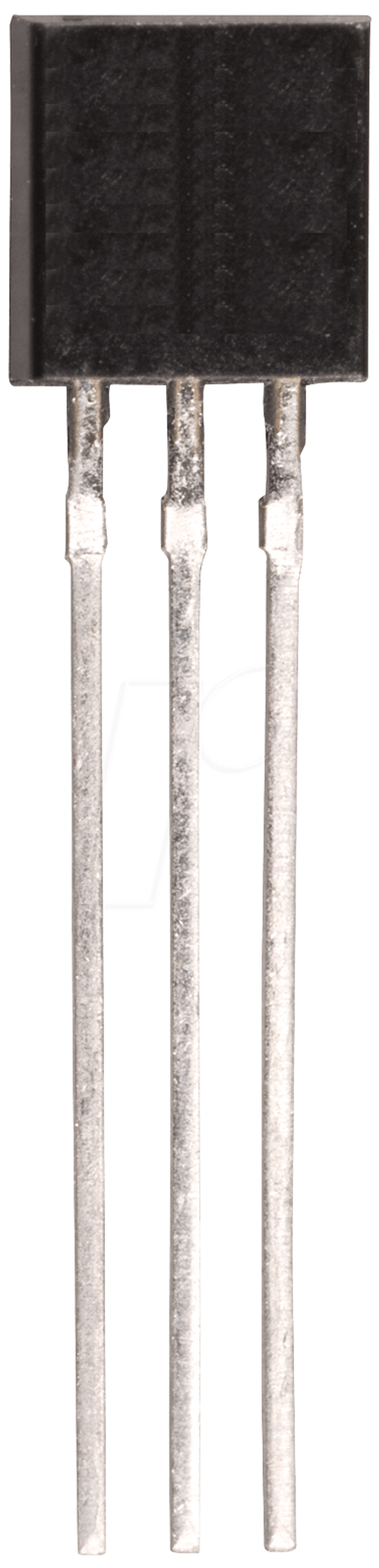
Pin Configuration
The BS250P is available in a TO-92 package with the following pin configuration:
| Pin Number | Pin Name | Description |
|---|---|---|
| 1 | Gate | Controls the MOSFET switching |
| 2 | Source | Connected to the positive voltage |
| 3 | Drain | Connected to the load |
Usage Instructions
How to Use the BS250P in a Circuit
Basic Circuit Setup:
- Connect the Source pin to the positive voltage supply.
- Connect the Drain pin to the load.
- Use a resistor (typically 10kΩ) between the Gate and Source to ensure the MOSFET remains off when no signal is applied to the Gate.
- Apply a negative voltage to the Gate relative to the Source to turn the MOSFET on.
Gate Drive Voltage:
- Ensure the Gate-Source voltage (VGS) is within the specified range (-2V to -10V) for proper operation.
- Avoid exceeding the maximum Gate-Source voltage (±20V) to prevent damage.
Load Considerations:
- Ensure the load current does not exceed the maximum continuous drain current (-0.25A).
- Use a heatsink or proper thermal management if operating near the maximum power dissipation.
Example Circuit with Arduino UNO
The BS250P can be used with an Arduino UNO for switching a low-power load. Below is an example:
Circuit Description:
- The BS250P is used to control an LED connected to a 12V power supply.
- The Arduino pin provides the Gate signal to turn the MOSFET on or off.
Circuit Diagram:
Arduino Pin (Digital Output) ----[1kΩ]---- Gate (BS250P)
Source (BS250P) ----------------- +12V
Drain (BS250P) ------------------ LED ---- Resistor ---- GND
Arduino Code:
// Example code to control BS250P with Arduino UNO
const int mosfetGatePin = 9; // Pin connected to the Gate of BS250P

void setup() {
  pinMode(mosfetGatePin, OUTPUT); // Set the pin as an output
}

void loop() {
  digitalWrite(mosfetGatePin, LOW);
  // Apply LOW signal to turn the MOSFET ON (LED ON)
  delay(1000); // Wait for 1 second

  digitalWrite(mosfetGatePin, HIGH);
  // Apply HIGH signal to turn the MOSFET OFF (LED OFF)
  delay(1000); // Wait for 1 second
}
Important Considerations:
- Use a pull-up resistor (e.g., 10kΩ) between the Gate and Source to ensure the MOSFET remains off when no signal is applied.
- Ensure the Arduino output pin voltage is sufficient to drive the Gate (typically 5V for logic-level operation).
- Avoid exceeding the maximum ratings for voltage, current, and power dissipation.
Troubleshooting and FAQs
Common Issues and Solutions:
MOSFET Not Switching Properly:
- Cause: Insufficient Gate-Source voltage.
- Solution: Ensure the Gate voltage is within the specified range (-2V to -10V).
Excessive Heat Generation:
- Cause: Operating near or above the maximum power dissipation.
- Solution: Use a heatsink or reduce the load current.
MOSFET Always On or Off:
- Cause: Missing pull-up or pull-down resistor on the Gate.
- Solution: Add a 10kΩ resistor between the Gate and Source.
Damaged MOSFET:
- Cause: Exceeding maximum voltage or current ratings.
- Solution: Verify the circuit design and ensure all parameters are within the specified limits.
FAQs:
Q1: Can the BS250P handle high-power loads?
A1: No, the BS250P is designed for low-power applications with a maximum continuous drain current of -0.25A.
Q2: Can I use the BS250P with a 3.3V microcontroller?
A2: Yes, but ensure the Gate-Source voltage is sufficient to fully turn on the MOSFET. A logic-level MOSFET may be more suitable for 3.3V systems.
Q3: What is the purpose of the pull-up resistor on the Gate?
A3: The pull-up resistor ensures the MOSFET remains off when no signal is applied to the Gate, preventing unintended switching.
Q4: Can the BS250P be used for AC switching?
A4: No, the BS250P is designed for DC applications and is not suitable for AC switching without additional circuitry.
By following this documentation, users can effectively integrate the BS250P into their electronic projects while avoiding common pitfalls.