How to Use EZ PH Circuit: Examples, Pinouts, and Specs
Introduction
The EZ PH Circuit (Manufacturer Part ID: 5016-EZO-PH-ND) by Atlas Scientific is a highly accurate and versatile pH measurement circuit. It is designed to interface with pH probes and convert their analog signals into digital data for precise pH readings. This component is ideal for applications requiring real-time pH monitoring, such as water quality testing, hydroponics, aquariums, and laboratory experiments.
The EZ PH Circuit simplifies the process of integrating pH measurement into electronic systems by providing a compact, pre-calibrated solution that can communicate with microcontrollers via UART or I2C protocols.
Explore Projects Built with EZ PH Circuit
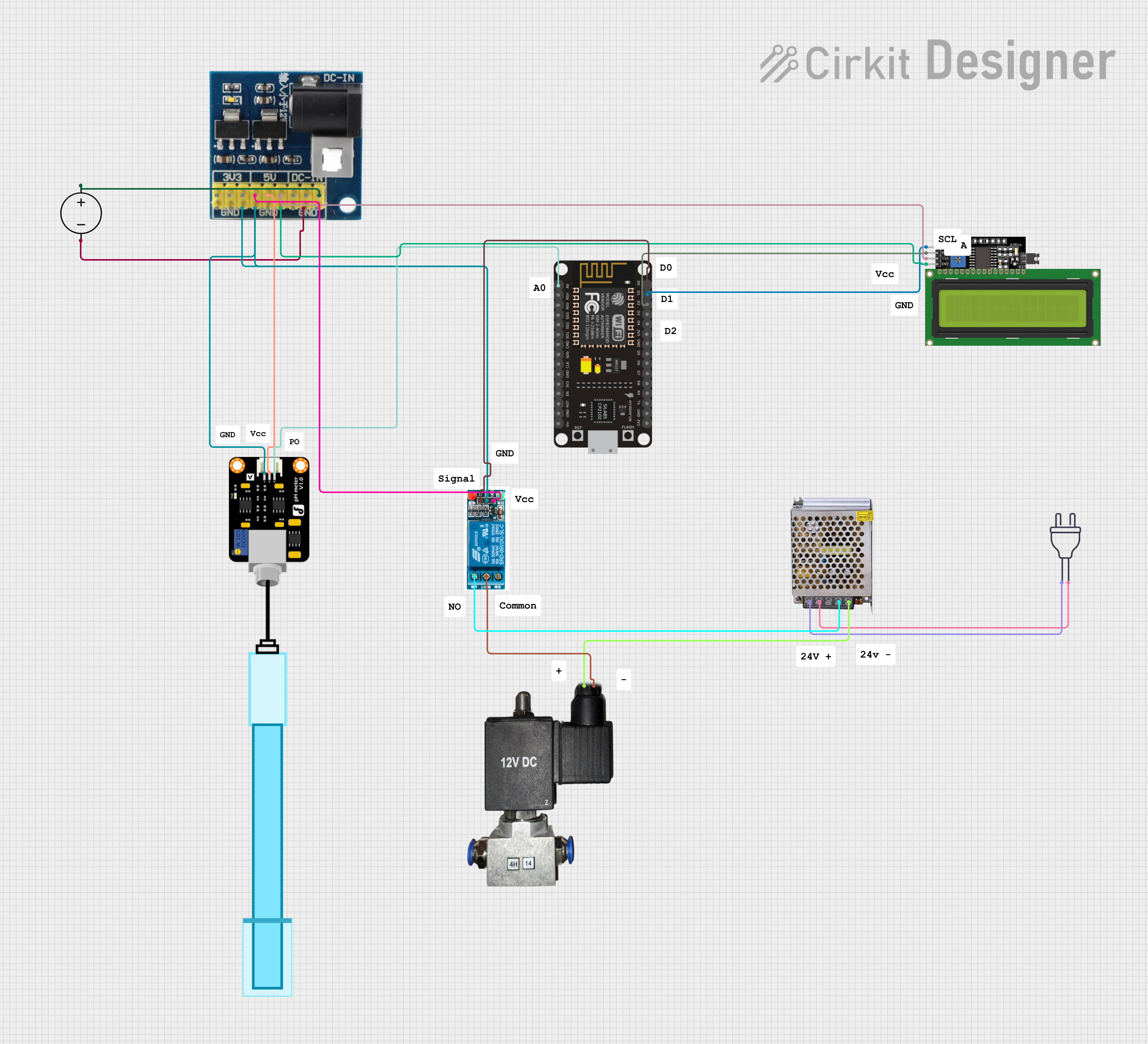
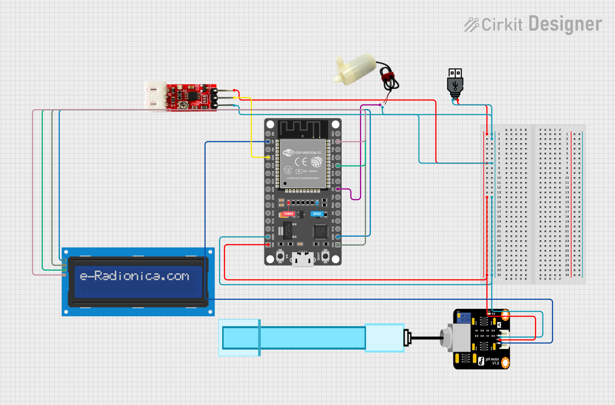
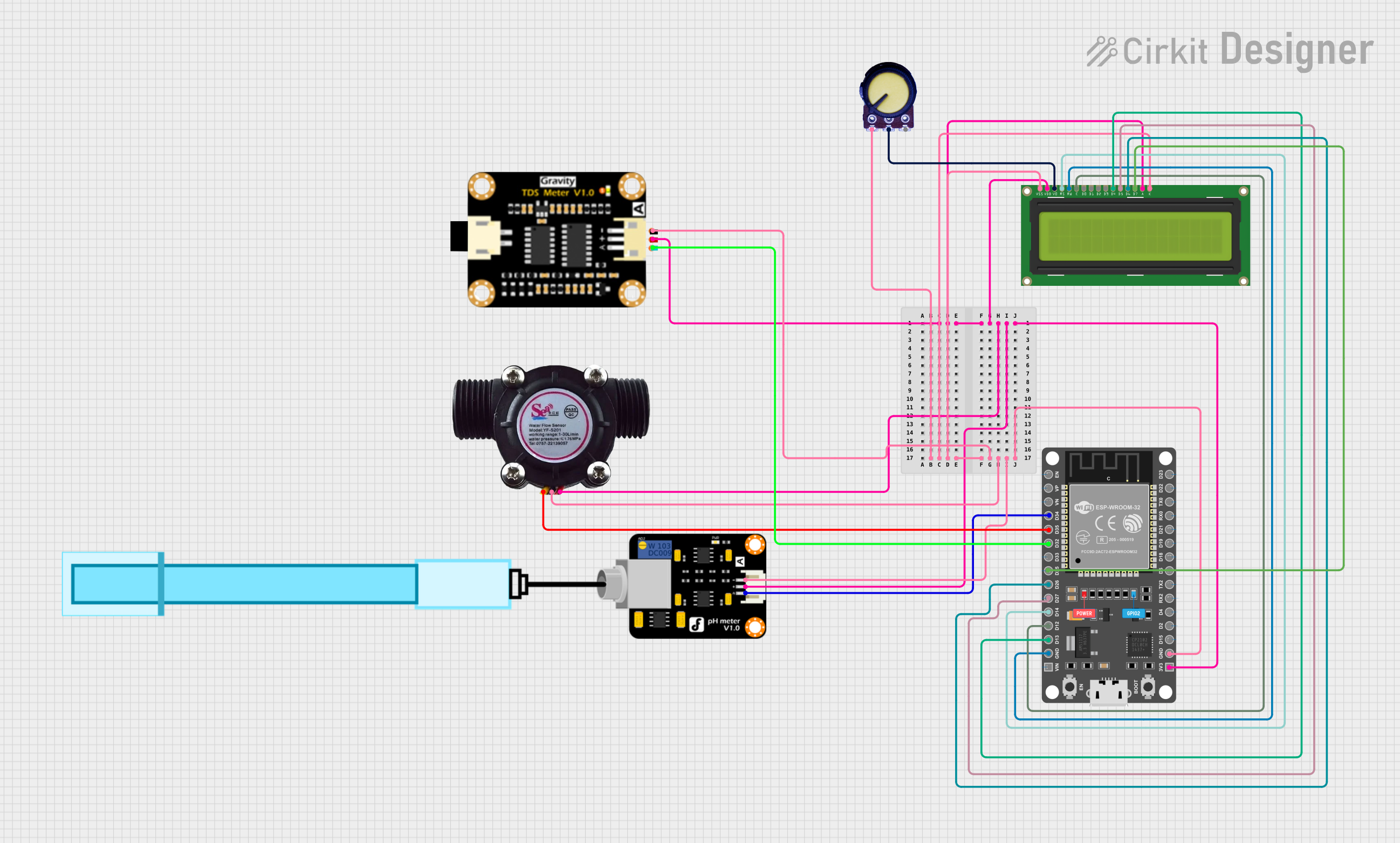

Explore Projects Built with EZ PH Circuit
Technical Specifications
Below are the key technical details of the EZ PH Circuit:
| Parameter | Value |
|---|---|
| Operating Voltage | 3.3V to 5.0V DC |
| Operating Current | ~4mA |
| Communication Protocols | UART (default) or I2C |
| pH Range | 0.00 to 14.00 pH |
| Accuracy | ±0.002 pH |
| Calibration | Single-point, two-point, or three-point calibration supported |
| Dimensions | 13.97mm x 20.32mm (0.55" x 0.8") |
| Operating Temperature | 0°C to 50°C |
| Supported Probes | Compatible with most standard pH probes |
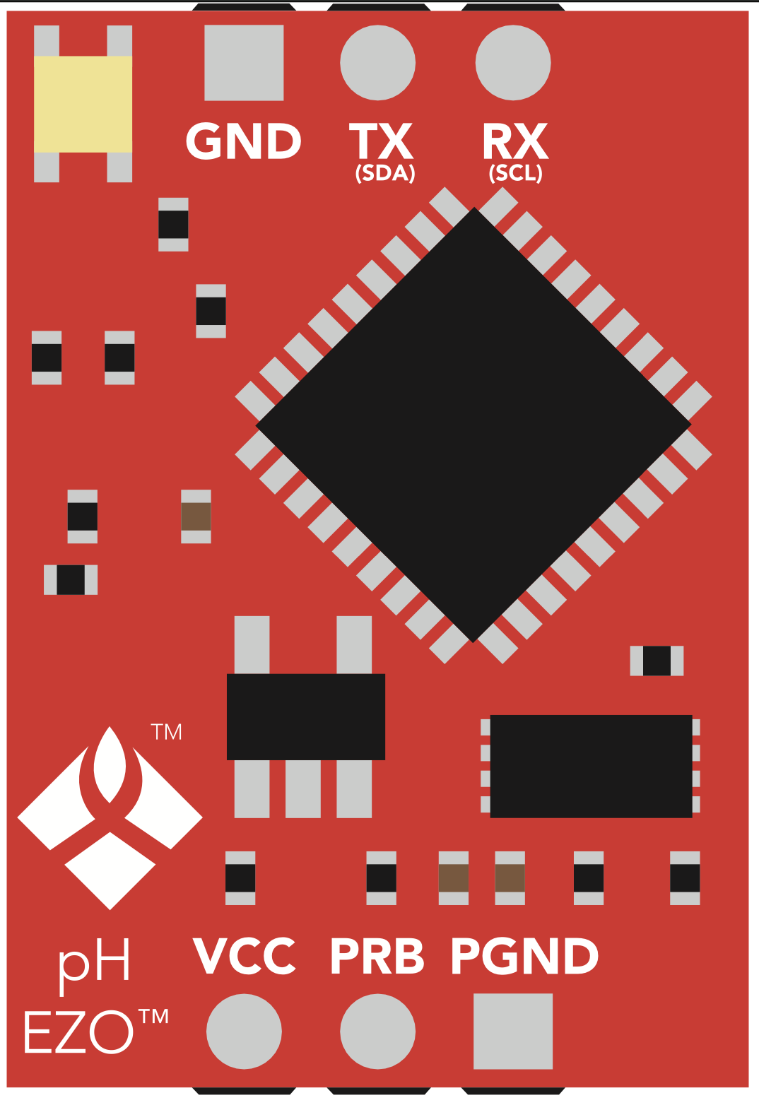
Pin Configuration and Descriptions
The EZ PH Circuit has a total of 6 pins. The table below describes each pin:
| Pin Name | Pin Number | Description |
|---|---|---|
| VCC | 1 | Power input (3.3V to 5.0V DC). Connect to the power supply. |
| GND | 2 | Ground connection. Connect to the system ground. |
| TX | 3 | UART Transmit pin. Sends data to the microcontroller. |
| RX | 4 | UART Receive pin. Receives data from the microcontroller. |
| SDA | 5 | I2C Data line. Used for communication in I2C mode. |
| SCL | 6 | I2C Clock line. Used for communication in I2C mode. |
Note: By default, the circuit operates in UART mode. To switch to I2C mode, send the appropriate command via UART.
Usage Instructions
How to Use the EZ PH Circuit in a Circuit
- Power the Circuit: Connect the VCC pin to a 3.3V or 5.0V power source and the GND pin to the system ground.
- Connect the pH Probe: Attach a compatible pH probe to the BNC connector on the circuit.
- Choose Communication Protocol:
- For UART: Connect the TX and RX pins to the corresponding UART pins on your microcontroller.
- For I2C: Connect the SDA and SCL pins to the I2C bus of your microcontroller.
- Calibrate the Circuit: Perform a single-point, two-point, or three-point calibration using standard pH buffer solutions (e.g., pH 4.0, 7.0, and 10.0).
- Read pH Data: Use the appropriate commands to retrieve pH readings from the circuit.
Important Considerations and Best Practices
- Calibration: Regular calibration ensures accurate readings. Always use fresh buffer solutions for calibration.
- Temperature Compensation: For best results, use a temperature sensor to compensate for temperature variations in the solution.
- Probe Maintenance: Clean the pH probe regularly and store it in a pH storage solution to prolong its lifespan.
- Avoid Electrical Noise: Place the circuit away from high-frequency noise sources to prevent interference.
Example: Using the EZ PH Circuit with Arduino UNO
Below is an example of how to interface the EZ PH Circuit with an Arduino UNO using UART:
#include <SoftwareSerial.h>

// Define RX and TX pins for SoftwareSerial
SoftwareSerial mySerial(10, 11); // RX = pin 10, TX = pin 11

void setup() {
  Serial.begin(9600);          // Start the hardware serial for debugging
  mySerial.begin(9600);        // Start the software serial for EZ PH Circuit

  Serial.println("EZ PH Circuit Initialized");
  delay(1000);                 // Allow the circuit to stabilize
}

void loop() {
  // Request pH reading from the circuit
  mySerial.print("R\r");       // Send the "R" command to request a reading
  delay(1000);                 // Wait for the circuit to process the command

  // Check if data is available from the circuit
  if (mySerial.available()) {
    String pHReading = "";
    while (mySerial.available()) {
      char c = mySerial.read(); // Read each character from the circuit
      pHReading += c;           // Append the character to the reading string
    }
    Serial.print("pH: ");       // Print the pH reading to the Serial Monitor
    Serial.println(pHReading);
  }
}
Note: Ensure the RX and TX pins of the EZ PH Circuit are connected to the correct pins on the Arduino UNO.
Troubleshooting and FAQs
Common Issues and Solutions
No Data from the Circuit:
- Ensure the circuit is powered correctly (3.3V to 5.0V).
- Verify the communication protocol (UART or I2C) and connections.
- Check the baud rate (default is 9600 for UART).
Inaccurate pH Readings:
- Perform a fresh calibration using standard buffer solutions.
- Ensure the pH probe is clean and properly maintained.
- Use temperature compensation if the solution temperature varies significantly.
Circuit Not Responding to Commands:
- Confirm that the correct command format is used (e.g., "R\r" for reading).
- Check for loose or incorrect wiring.
FAQs
Q1: Can I use the EZ PH Circuit with a Raspberry Pi?
Yes, the circuit can be used with a Raspberry Pi via UART or I2C. Ensure the voltage levels are compatible (use a level shifter if necessary).
Q2: How often should I calibrate the circuit?
Calibration frequency depends on usage. For critical applications, calibrate daily. For less demanding applications, weekly calibration may suffice.
Q3: What is the default I2C address of the circuit?
The default I2C address is 0x63. You can change it using the appropriate command.
Q4: Can the circuit measure ORP (Oxidation-Reduction Potential)?
No, the EZ PH Circuit is specifically designed for pH measurement. For ORP, use a dedicated ORP circuit.
By following this documentation, you can effectively integrate the EZ PH Circuit into your projects and achieve accurate pH measurements.