How to Use RZ60S: Examples, Pinouts, and Specs
Introduction
The RZ60S is a type of resistor, commonly used in electronic circuits to control current flow, divide voltages, or provide biasing. It is a passive component that plays a critical role in ensuring the proper functioning of analog and digital circuits. The RZ60S is characterized by its resistance value, power rating, and tolerance, making it versatile for a wide range of applications.
Explore Projects Built with RZ60S


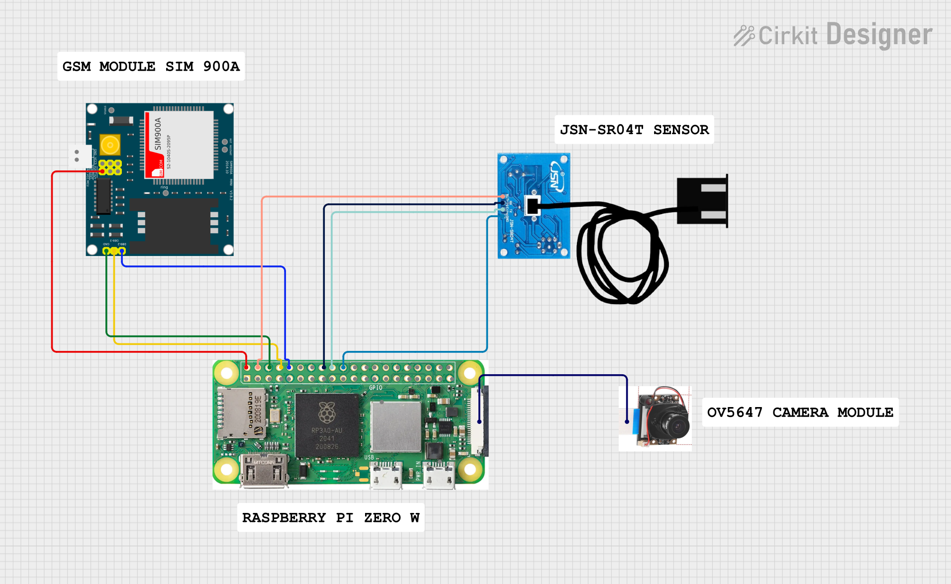
Explore Projects Built with RZ60S
Common Applications and Use Cases
- Current limiting in LED circuits
- Voltage division in sensor interfacing
- Biasing transistors in amplifier circuits
- Pull-up or pull-down resistors in digital logic circuits
- Protection of sensitive components from excessive current
Technical Specifications
The RZ60S resistor is available in various resistance values and power ratings. Below are the general specifications:
| Parameter | Value |
|---|---|
| Resistance Range | 1 Ω to 1 MΩ |
| Power Rating | 0.25 W (1/4 W) |
| Tolerance | ±5% (standard) |
| Temperature Coefficient | ±200 ppm/°C |
| Maximum Voltage Rating | 250 V |
| Package Type | Axial lead |
Pin Configuration and Descriptions
The RZ60S is a two-terminal component with no polarity. The leads are used to connect the resistor in a circuit. Below is the pin description:
| Pin | Description |
|---|---|
| Lead 1 | Connects to one side of the circuit |
| Lead 2 | Connects to the other side of the circuit |
Usage Instructions
How to Use the RZ60S in a Circuit
- Determine the Required Resistance Value: Use Ohm's Law (V = IR) to calculate the resistance needed for your application.
- Select the Appropriate Power Rating: Ensure the resistor can handle the power dissipation, calculated as ( P = I^2R ) or ( P = V^2/R ).
- Connect the Resistor: Solder the leads to the circuit board or use a breadboard for prototyping. The RZ60S has no polarity, so orientation does not matter.
- Verify the Circuit: Use a multimeter to confirm the resistance value and ensure proper connections.
Important Considerations and Best Practices
- Avoid Overloading: Ensure the resistor's power rating is not exceeded to prevent overheating or damage.
- Check Tolerance: For precision applications, account for the ±5% tolerance in resistance value.
- Temperature Effects: Be aware of the temperature coefficient, as resistance may vary slightly with temperature changes.
- Use in Voltage Dividers: When using the RZ60S in a voltage divider, ensure the total resistance is appropriate for the desired voltage drop and current.
Example: Using the RZ60S with an Arduino UNO
The RZ60S can be used as a current-limiting resistor for an LED connected to an Arduino UNO. Below is an example circuit and code:
Circuit Setup
- Connect one lead of the RZ60S (e.g., 220 Ω) to the Arduino's digital pin (e.g., pin 13).
- Connect the other lead of the resistor to the anode (+) of the LED.
- Connect the cathode (-) of the LED to the Arduino's GND pin.
Arduino Code
// Example code to blink an LED using the RZ60S resistor

const int ledPin = 13; // Pin connected to the LED through the RZ60S resistor

void setup() {
  pinMode(ledPin, OUTPUT); // Set the LED pin as an output
}

void loop() {
  digitalWrite(ledPin, HIGH); // Turn the LED on
  delay(1000); // Wait for 1 second
  digitalWrite(ledPin, LOW); // Turn the LED off
  delay(1000); // Wait for 1 second
}
Troubleshooting and FAQs
Common Issues
Resistor Overheating:
- Cause: Power dissipation exceeds the resistor's rating.
- Solution: Use a resistor with a higher power rating or reduce the current/voltage.
Incorrect Resistance Value:
- Cause: Misreading the color code or using the wrong resistor.
- Solution: Double-check the color code or measure the resistance with a multimeter.
LED Not Lighting Up:
- Cause: Incorrect resistor value or loose connections.
- Solution: Verify the resistor value and ensure all connections are secure.
FAQs
Q: Can I use the RZ60S in high-frequency circuits?
A: The RZ60S is suitable for most general-purpose applications, but for high-frequency circuits, consider resistors with lower parasitic inductance.Q: How do I calculate the resistor value for an LED?
A: Use the formula ( R = (V_{supply} - V_{LED}) / I_{LED} ), where ( V_{supply} ) is the supply voltage, ( V_{LED} ) is the forward voltage of the LED, and ( I_{LED} ) is the desired current.Q: Can I use multiple RZ60S resistors in parallel or series?
A: Yes, resistors can be combined in series to increase resistance or in parallel to decrease resistance. Ensure the combined power rating meets your requirements.