How to Use SR232: Examples, Pinouts, and Specs
Introduction
The SR232 is a serial communication interface standard designed for asynchronous data transmission between devices over short distances. It is widely used in applications requiring simple, reliable, and low-speed data exchange. The SR232 standard typically employs a 9-pin (DB9) or 25-pin (DB25) connector and supports various baud rates, making it versatile for numerous use cases.
Explore Projects Built with SR232


Explore Projects Built with SR232
Common Applications and Use Cases
- Communication between computers and peripheral devices (e.g., printers, modems).
- Industrial automation systems for device-to-device communication.
- Debugging and programming of embedded systems.
- Data logging and monitoring in laboratory equipment.
- Legacy system integration in older hardware setups.
Technical Specifications
Key Technical Details
- Communication Type: Asynchronous serial communication.
- Voltage Levels: ±3V to ±15V (logic high: -3V to -15V, logic low: +3V to +15V).
- Baud Rate: Typically up to 115,200 bps (bits per second), depending on the application.
- Connector Types: DB9 (9-pin) or DB25 (25-pin).
- Maximum Cable Length: Up to 15 meters (50 feet) at 19,200 bps.
- Data Format: 1 start bit, 5-8 data bits, optional parity bit, and 1-2 stop bits.
- Flow Control: Hardware (RTS/CTS) or software (XON/XOFF).
Pin Configuration and Descriptions
DB9 Connector Pinout
| Pin Number | Name | Direction | Description |
|---|---|---|---|
| 1 | DCD (Data Carrier Detect) | Input | Indicates the presence of a carrier signal. |
| 2 | RXD (Receive Data) | Input | Data received by the device. |
| 3 | TXD (Transmit Data) | Output | Data transmitted by the device. |
| 4 | DTR (Data Terminal Ready) | Output | Indicates the device is ready to communicate. |
| 5 | GND (Ground) | - | Signal ground. |
| 6 | DSR (Data Set Ready) | Input | Indicates the connected device is ready. |
| 7 | RTS (Request to Send) | Output | Used for hardware flow control. |
| 8 | CTS (Clear to Send) | Input | Used for hardware flow control. |
| 9 | RI (Ring Indicator) | Input | Indicates an incoming call (modem use). |
DB25 Connector Pinout
| Pin Number | Name | Direction | Description |
|---|---|---|---|
| 1 | GND (Ground) | - | Signal ground. |
| 2 | TXD (Transmit Data) | Output | Data transmitted by the device. |
| 3 | RXD (Receive Data) | Input | Data received by the device. |
| 4 | RTS (Request to Send) | Output | Used for hardware flow control. |
| 5 | CTS (Clear to Send) | Input | Used for hardware flow control. |
| 6 | DSR (Data Set Ready) | Input | Indicates the connected device is ready. |
| 7 | GND (Ground) | - | Signal ground. |
| 8 | DCD (Data Carrier Detect) | Input | Indicates the presence of a carrier signal. |
| 20 | DTR (Data Terminal Ready) | Output | Indicates the device is ready to communicate. |
| 22 | RI (Ring Indicator) | Input | Indicates an incoming call (modem use). |
Usage Instructions
How to Use the SR232 in a Circuit
Connect the SR232 to the Devices:
- Use a DB9 or DB25 cable to connect the SR232 interface of the two devices.
- Ensure the pinout matches the devices' requirements (e.g., TXD of one device connects to RXD of the other).
Set the Communication Parameters:
- Configure the baud rate, data bits, parity, and stop bits on both devices to match.
- If using hardware flow control, ensure RTS and CTS are properly connected.
Power the Devices:
- Ensure both devices are powered on and ready for communication.
Test the Connection:
- Use a terminal program (e.g., PuTTY or Tera Term) to send and receive data.
- Verify the data is transmitted and received correctly.
Important Considerations and Best Practices
- Cable Length: Keep the cable length within the standard limit (15 meters at 19,200 bps) to avoid signal degradation.
- Voltage Levels: Ensure the devices comply with the SR232 voltage level specifications to prevent damage.
- Grounding: Properly ground the devices to avoid noise and interference.
- Loopback Testing: For troubleshooting, perform a loopback test by connecting TXD to RXD on the same device.
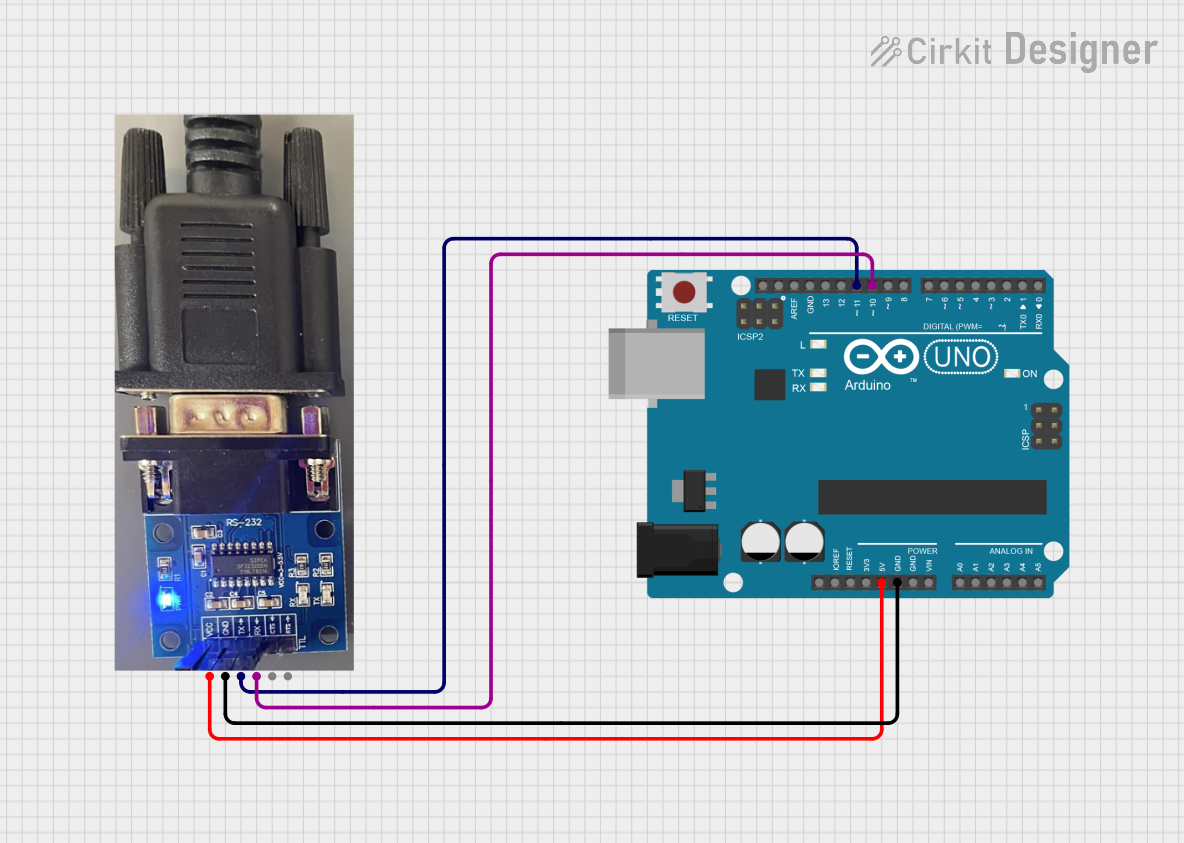
Example: Connecting SR232 to an Arduino UNO
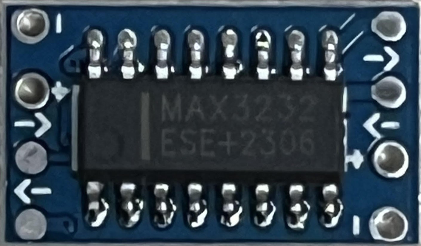
The SR232 can be interfaced with an Arduino UNO using a MAX232 level shifter IC to convert the Arduino's TTL logic levels to SR232 voltage levels.
Circuit Diagram
- Connect the MAX232 IC between the Arduino and the SR232 device.
- TXD (Arduino) → T1IN (MAX232) → T1OUT (MAX232) → RXD (SR232).
- RXD (Arduino) ← R1OUT (MAX232) ← R1IN (MAX232) ← TXD (SR232).
Arduino Code Example
// Example code for SR232 communication with Arduino UNO
#include <SoftwareSerial.h>

// Define RX and TX pins for SoftwareSerial
SoftwareSerial mySerial(10, 11); // RX = pin 10, TX = pin 11

void setup() {
  // Start the hardware serial communication
  Serial.begin(9600); // Baud rate for Arduino Serial Monitor
  // Start the SR232 communication
  mySerial.begin(9600); // Baud rate for SR232 device
  Serial.println("SR232 Communication Initialized");
}

void loop() {
  // Check if data is available from the SR232 device
  if (mySerial.available()) {
    char received = mySerial.read(); // Read the incoming data
    Serial.print("Received: ");
    Serial.println(received); // Print the received data to Serial Monitor
  }

  // Send data to the SR232 device
  if (Serial.available()) {
    char toSend = Serial.read(); // Read data from Serial Monitor
    mySerial.write(toSend); // Send the data to the SR232 device
    Serial.print("Sent: ");
    Serial.println(toSend); // Print the sent data to Serial Monitor
  }
}
Troubleshooting and FAQs
Common Issues and Solutions
No Data Transmission:
- Cause: Mismatched baud rate or communication parameters.
- Solution: Verify and match the baud rate, data bits, parity, and stop bits on both devices.
Data Corruption:
- Cause: Excessive cable length or electrical noise.
- Solution: Use a shorter cable and ensure proper grounding.
No Response from Device:
- Cause: Incorrect wiring or damaged cable.
- Solution: Check the pin connections and replace the cable if necessary.
Loopback Test Fails:
- Cause: Faulty SR232 interface or level shifter.
- Solution: Test the SR232 interface with another device or replace the level shifter.
FAQs
Q: Can I use SR232 for long-distance communication?
- A: No, SR232 is designed for short distances (up to 15 meters). For longer distances, consider RS485 or RS422.
Q: How do I test if my SR232 port is working?
- A: Perform a loopback test by connecting TXD to RXD and sending data. If the data is echoed back, the port is functional.
Q: What is the difference between DB9 and DB25 connectors?
- A: DB9 is a 9-pin connector commonly used for SR232, while DB25 is a 25-pin connector with additional signals for older devices.
Q: Can I connect SR232 directly to an Arduino?
- A: No, you need a level shifter (e.g., MAX232) to convert the Arduino's TTL logic levels to SR232 voltage levels.