Cirkit Designer Logo
Cirkit Designer
Your all-in-one circuit design IDE
Home / 
Component Documentation

How to Use Obstacle Detector: Examples, Pinouts, and Specs

Image of Obstacle Detector
Cirkit Designer LogoDesign with Obstacle Detector in Cirkit Designer

Introduction

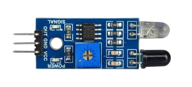
The Obstacle Detector (IR Module), manufactured by Arduino, is a compact and efficient sensor designed to detect obstacles in the path of a moving object. It uses infrared (IR) technology to sense the presence of objects within its detection range. This module is widely used in robotics, autonomous vehicles, and other applications where collision prevention is critical. Its simple design and ease of integration make it a popular choice for both hobbyists and professionals.

Explore Projects Built with Obstacle Detector

Use Cirkit Designer to design, explore, and prototype these projects online. Some projects support real-time simulation. Click "Open Project" to start designing instantly!
Arduino UNO-Based Obstacle-Avoiding Robot with Ultrasonic Sensor and L298N Motor Driver
Image of VacuumCleaner: A project utilizing Obstacle Detector in a practical application
This circuit is an obstacle-avoiding robot controlled by an Arduino UNO. It uses an HC-SR04 ultrasonic sensor to detect obstacles, a Tower Pro SG90 servo to adjust the sensor's direction, and an L298N motor driver to control multiple DC motors for movement. The Arduino code handles obstacle detection and navigation by moving the robot forward, backward, or turning based on the distance measured by the ultrasonic sensor.
Cirkit Designer LogoOpen Project in Cirkit Designer
Arduino UNO Obstacle-Avoiding Robot with Ultrasonic Sensor and Servo
Image of robot: A project utilizing Obstacle Detector in a practical application
This circuit is an obstacle-avoiding robot controlled by an Arduino UNO. It uses an HC-SR04 ultrasonic sensor to detect obstacles and an L298N motor driver to control two motors, with a servo motor scanning for obstacles at different angles. The robot moves forward, and upon detecting an obstacle, it backs up and turns to avoid it.
Cirkit Designer LogoOpen Project in Cirkit Designer
Arduino UNO Obstacle-Avoiding Robot with Ultrasonic Sensor and Servo
Image of robot car: A project utilizing Obstacle Detector in a practical application
This circuit is an obstacle-avoiding robot controlled by an Arduino UNO. It uses an HC-SR04 ultrasonic sensor to detect obstacles, an L298N motor driver to control two DC motors, and a Tower Pro SG90 servo to scan for obstacles at different angles. The robot moves forward, backward, or stops based on the distance readings from the ultrasonic sensor.
Cirkit Designer LogoOpen Project in Cirkit Designer
Arduino UNO Obstacle Avoidance Robot with Ultrasonic Sensor and Servo
Image of robot: A project utilizing Obstacle Detector in a practical application
This circuit is an obstacle avoidance robot controlled by an Arduino UNO. It uses an ultrasonic sensor to detect obstacles, two DC motors for movement, a servo motor for scanning, and an L298N motor driver for motor control. The robot moves forward until an obstacle is detected, then scans for a clear path and turns accordingly.
Cirkit Designer LogoOpen Project in Cirkit Designer

Explore Projects Built with Obstacle Detector

Use Cirkit Designer to design, explore, and prototype these projects online. Some projects support real-time simulation. Click "Open Project" to start designing instantly!
Image of VacuumCleaner: A project utilizing Obstacle Detector in a practical application
Arduino UNO-Based Obstacle-Avoiding Robot with Ultrasonic Sensor and L298N Motor Driver
This circuit is an obstacle-avoiding robot controlled by an Arduino UNO. It uses an HC-SR04 ultrasonic sensor to detect obstacles, a Tower Pro SG90 servo to adjust the sensor's direction, and an L298N motor driver to control multiple DC motors for movement. The Arduino code handles obstacle detection and navigation by moving the robot forward, backward, or turning based on the distance measured by the ultrasonic sensor.
Cirkit Designer LogoOpen Project in Cirkit Designer
Image of robot: A project utilizing Obstacle Detector in a practical application
Arduino UNO Obstacle-Avoiding Robot with Ultrasonic Sensor and Servo
This circuit is an obstacle-avoiding robot controlled by an Arduino UNO. It uses an HC-SR04 ultrasonic sensor to detect obstacles and an L298N motor driver to control two motors, with a servo motor scanning for obstacles at different angles. The robot moves forward, and upon detecting an obstacle, it backs up and turns to avoid it.
Cirkit Designer LogoOpen Project in Cirkit Designer
Image of robot car: A project utilizing Obstacle Detector in a practical application
Arduino UNO Obstacle-Avoiding Robot with Ultrasonic Sensor and Servo
This circuit is an obstacle-avoiding robot controlled by an Arduino UNO. It uses an HC-SR04 ultrasonic sensor to detect obstacles, an L298N motor driver to control two DC motors, and a Tower Pro SG90 servo to scan for obstacles at different angles. The robot moves forward, backward, or stops based on the distance readings from the ultrasonic sensor.
Cirkit Designer LogoOpen Project in Cirkit Designer
Image of robot: A project utilizing Obstacle Detector in a practical application
Arduino UNO Obstacle Avoidance Robot with Ultrasonic Sensor and Servo
This circuit is an obstacle avoidance robot controlled by an Arduino UNO. It uses an ultrasonic sensor to detect obstacles, two DC motors for movement, a servo motor for scanning, and an L298N motor driver for motor control. The robot moves forward until an obstacle is detected, then scans for a clear path and turns accordingly.
Cirkit Designer LogoOpen Project in Cirkit Designer

Common Applications and Use Cases

  • Autonomous robots for obstacle avoidance
  • Line-following robots
  • Proximity detection in industrial automation
  • Smart home devices for motion sensing
  • Collision prevention in drones and vehicles

Technical Specifications

The following table outlines the key technical details of the Arduino IR Module:

Parameter Specification
Operating Voltage 3.3V to 5V DC
Operating Current 20mA (typical)
Detection Range 2cm to 30cm (adjustable via potentiometer)
Output Type Digital (High/Low)
IR Wavelength 940nm
Dimensions 3.1cm x 1.5cm x 0.7cm
Operating Temperature -10°C to 50°C

Pin Configuration and Descriptions

The IR Module has a 3-pin interface, as described in the table below:

Pin Name Description
1 VCC Power supply pin (3.3V to 5V DC)
2 GND Ground pin
3 OUT Digital output pin (High when no obstacle, Low when obstacle detected)

Usage Instructions

How to Use the Component in a Circuit

  1. Power the Module: Connect the VCC pin to a 3.3V or 5V power source and the GND pin to the ground of your circuit.
  2. Connect the Output: Attach the OUT pin to a digital input pin on your microcontroller (e.g., Arduino UNO).
  3. Adjust the Sensitivity: Use the onboard potentiometer to adjust the detection range of the sensor. Turn clockwise to increase the range and counterclockwise to decrease it.
  4. Test the Module: Place an object within the detection range and observe the output pin. The OUT pin will go LOW when an obstacle is detected.

Important Considerations and Best Practices

  • Ambient Light Interference: The IR Module may be affected by strong ambient light. Use it in controlled lighting conditions for optimal performance.
  • Mounting Position: Ensure the sensor is mounted at an appropriate angle to detect obstacles effectively.
  • Power Supply: Use a stable power source to avoid erratic behavior.
  • Avoid Overheating: Prolonged exposure to high temperatures may degrade the sensor's performance.

Example Code for Arduino UNO

Below is an example code snippet to interface the IR Module with an Arduino UNO:

// Define the pin connected to the IR Module's OUT pin
const int IR_Sensor_Pin = 2; // Digital pin 2

// Define the onboard LED pin (for testing purposes)
const int LED_Pin = 13;

void setup() {
  pinMode(IR_Sensor_Pin, INPUT); // Set IR sensor pin as input
  pinMode(LED_Pin, OUTPUT);      // Set LED pin as output
  Serial.begin(9600);            // Initialize serial communication
}

void loop() {
  int sensorValue = digitalRead(IR_Sensor_Pin); // Read the sensor output

  if (sensorValue == LOW) {
    // Obstacle detected
    digitalWrite(LED_Pin, HIGH); // Turn on LED
    Serial.println("Obstacle detected!");
  } else {
    // No obstacle
    digitalWrite(LED_Pin, LOW);  // Turn off LED
    Serial.println("No obstacle.");
  }

  delay(100); // Small delay for stability
}

Troubleshooting and FAQs

Common Issues Users Might Face

  1. Sensor Not Detecting Obstacles:

    • Ensure the VCC and GND pins are connected properly.
    • Check the potentiometer adjustment and increase the detection range if needed.
    • Verify that the obstacle is within the sensor's detection range (2cm to 30cm).
  2. False Positives or Erratic Behavior:

    • Reduce ambient light interference by shielding the sensor.
    • Use a stable power supply to avoid fluctuations.
  3. Output Pin Always HIGH or LOW:

    • Inspect the wiring for loose connections.
    • Test the module with a multimeter to ensure it is functioning correctly.

Solutions and Tips for Troubleshooting

  • Testing the Module: Use an LED or multimeter to verify the output pin's behavior when an obstacle is placed in front of the sensor.
  • Recalibrating the Sensor: Adjust the potentiometer to fine-tune the detection range.
  • Replacing Components: If the module is damaged, consider replacing it with a new one.

By following this documentation, users can effectively integrate the Arduino IR Module into their projects and troubleshoot common issues with ease.