How to Use raspberry pi power switch: Examples, Pinouts, and Specs
Introduction
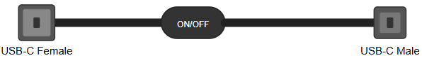
The Raspberry Pi Power Switch is a device designed to control the power supply to a Raspberry Pi. It allows users to safely turn the Raspberry Pi on or off without the need to unplug the power cable. This component is particularly useful for protecting the Raspberry Pi from sudden power interruptions, which can lead to data corruption or hardware damage.
Explore Projects Built with raspberry pi power switch

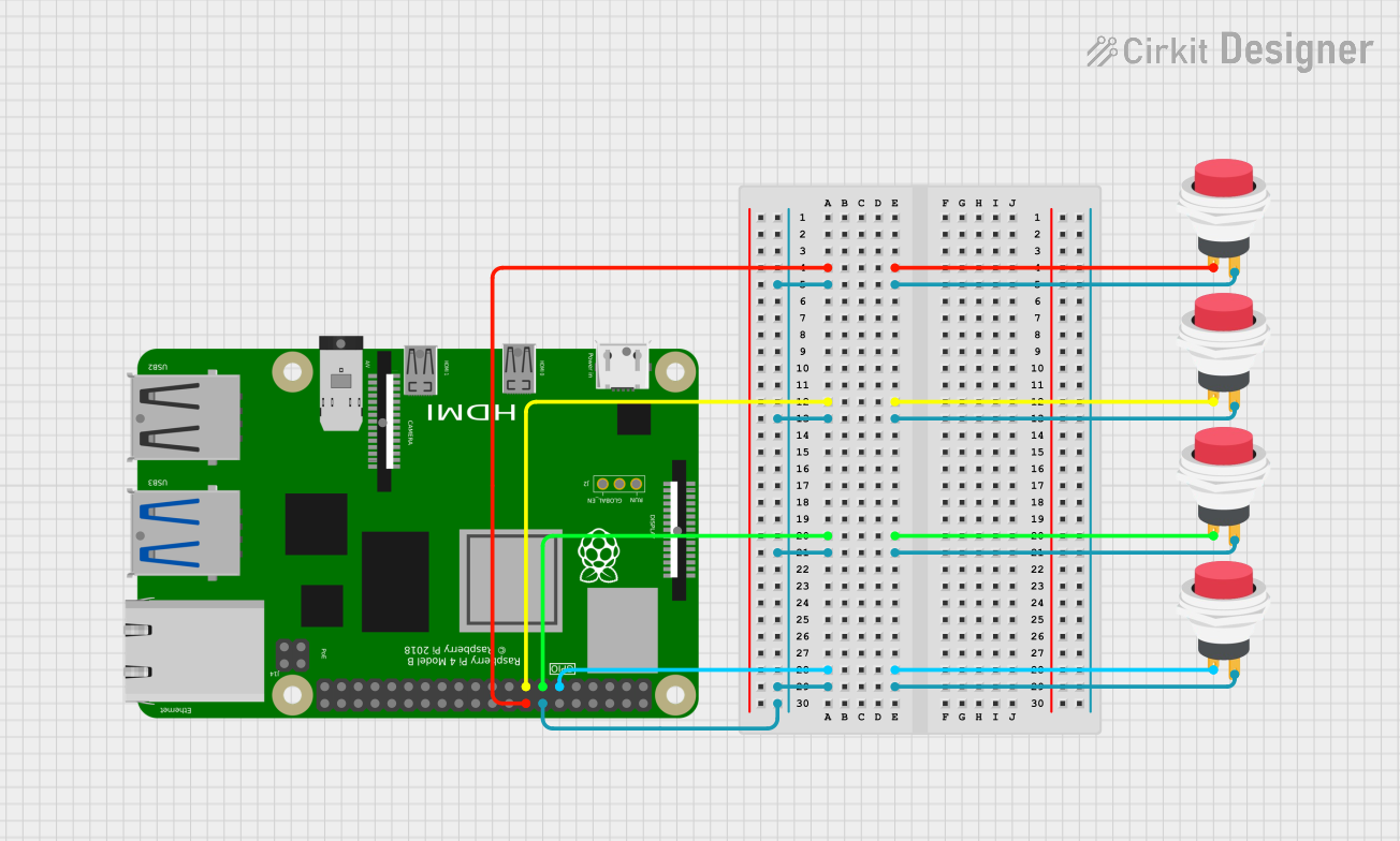
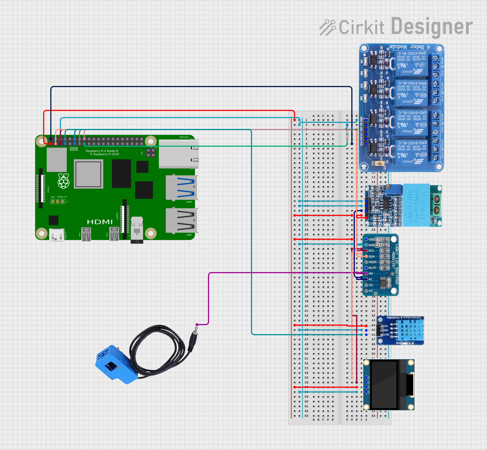
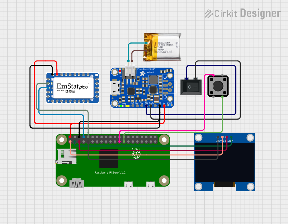
Explore Projects Built with raspberry pi power switch
Common Applications and Use Cases
- Safely powering on and off Raspberry Pi devices in embedded systems.
- Preventing SD card corruption caused by improper shutdowns.
- Convenient power management for Raspberry Pi-based projects, such as media centers, IoT devices, and robotics.
- Use in educational environments to simplify power control for students.
Technical Specifications
The Raspberry Pi Power Switch is typically designed to handle the power requirements of most Raspberry Pi models. Below are the general specifications:
| Parameter | Value |
|---|---|
| Input Voltage | 5V DC (via USB or GPIO header) |
| Output Voltage | 5V DC |
| Maximum Current | 3A (suitable for Raspberry Pi 4 and below) |
| Power Control Method | Physical toggle switch or push button |
| Connector Type | USB Type-C, Micro-USB, or GPIO header |
| Dimensions | Varies by model, typically compact |
Pin Configuration and Descriptions
If the power switch connects via the GPIO header, the pin configuration is as follows:
| Pin | Name | Description |
|---|---|---|
| 2 | 5V Power | Supplies 5V power to the Raspberry Pi. |
| 6 | Ground (GND) | Provides the ground connection for the circuit. |
| 7 | GPIO4 (Optional) | Used for software-based power control (if supported). |
Usage Instructions
How to Use the Raspberry Pi Power Switch
Connect the Power Switch:
- If using a USB-based power switch, connect the input side to a 5V power source (e.g., a USB power adapter) and the output side to the Raspberry Pi's power input port.
- If using a GPIO-based power switch, connect the pins as per the pin configuration table above.
Power On the Raspberry Pi:
- Toggle the switch to the "ON" position or press the power button to supply power to the Raspberry Pi.
Power Off the Raspberry Pi:
- Before turning off the power switch, ensure the Raspberry Pi has been properly shut down using the command:
sudo shutdown -h now - Once the shutdown process is complete, toggle the switch to the "OFF" position or press the power button.
- Before turning off the power switch, ensure the Raspberry Pi has been properly shut down using the command:
Important Considerations and Best Practices
- Always shut down the Raspberry Pi using the proper software command before turning off the power switch to avoid data corruption.
- Ensure the power switch can handle the current requirements of your Raspberry Pi model, especially if additional peripherals are connected.
- If using a GPIO-based power switch, ensure the connections are secure and match the pin configuration.
Example: Using the Power Switch with an Arduino UNO
If the power switch supports GPIO control, you can use an Arduino UNO to toggle the Raspberry Pi's power. Below is an example code snippet:
// Define the GPIO pin connected to the power switch
const int powerSwitchPin = 7;

void setup() {
  pinMode(powerSwitchPin, OUTPUT); // Set the pin as an output
  digitalWrite(powerSwitchPin, LOW); // Ensure the power is off initially
}

void loop() {
  // Example: Turn on the Raspberry Pi for 10 seconds, then turn it off
  digitalWrite(powerSwitchPin, HIGH); // Turn on the power
  delay(10000); // Wait for 10 seconds
  digitalWrite(powerSwitchPin, LOW); // Turn off the power
  delay(5000); // Wait for 5 seconds before repeating
}
Troubleshooting and FAQs
Common Issues and Solutions
Raspberry Pi Does Not Power On:
- Cause: Insufficient power supply or loose connections.
- Solution: Ensure the power adapter provides at least 5V and 3A. Check all connections.
Raspberry Pi Shuts Down Unexpectedly:
- Cause: Overcurrent or overheating.
- Solution: Verify that the power switch can handle the current requirements. Ensure proper cooling for the Raspberry Pi.
Data Corruption After Power Off:
- Cause: Improper shutdown before turning off the power switch.
- Solution: Always shut down the Raspberry Pi using the
sudo shutdown -h nowcommand before turning off the power.
FAQs
Q: Can I use the power switch with other devices?
A: Yes, the power switch can be used with other 5V devices, provided the current requirements are within the switch's specifications.
Q: Does the power switch support automatic shutdown?
A: Some advanced models include GPIO-based control for software-triggered shutdown. Check the product documentation for details.
Q: Is the power switch compatible with all Raspberry Pi models?
A: Most power switches are compatible with all Raspberry Pi models, but ensure the current rating matches your specific model's requirements.