How to Use stepdown 24v to 5v: Examples, Pinouts, and Specs
Introduction
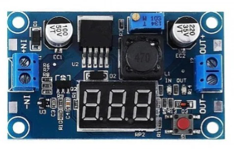
A stepdown converter, also known as a buck converter, reduces the voltage from 24 volts to 5 volts, allowing for efficient power conversion while maintaining a stable output voltage. This component is widely used in applications where devices require a lower voltage than the input supply. It is particularly useful in battery-powered systems, industrial automation, and embedded systems.
Explore Projects Built with stepdown 24v to 5v


Explore Projects Built with stepdown 24v to 5v
Common Applications and Use Cases
- Powering microcontrollers, sensors, and modules from a 24V power source
- Industrial control systems requiring 5V logic levels
- Battery-powered devices with a 24V input
- Automotive electronics for stepping down 24V vehicle power to 5V
- USB power supplies for charging or powering 5V devices
Technical Specifications
Below are the key technical details for a typical stepdown 24V to 5V converter:
| Parameter | Value |
|---|---|
| Input Voltage Range | 6V to 24V |
| Output Voltage | 5V ± 0.1V |
| Maximum Output Current | 3A (varies by model) |
| Efficiency | Up to 95% |
| Switching Frequency | 150 kHz to 300 kHz |
| Operating Temperature | -40°C to +85°C |
| Protection Features | Overcurrent, Overtemperature, |
| and Short-Circuit Protection |
Pin Configuration and Descriptions
The stepdown converter typically has the following pin configuration:
| Pin Name | Description |
|---|---|
| VIN | Input voltage pin (connect to 24V source) |
| GND | Ground pin (common ground for input/output) |
| VOUT | Output voltage pin (provides 5V output) |
| EN (optional) | Enable pin (used to turn the module on/off) |
Usage Instructions
How to Use the Component in a Circuit
Connect the Input Voltage (VIN):
Attach the 24V power source to the VIN pin. Ensure the input voltage is within the specified range (6V to 24V).Connect the Ground (GND):
Connect the ground of the power source and the load to the GND pin of the converter.Connect the Output Voltage (VOUT):
Attach the device or circuit requiring 5V to the VOUT pin. Verify that the load does not exceed the maximum output current rating.Optional Enable Pin (EN):
If the module has an enable pin, connect it to a logic HIGH (e.g., 5V) to activate the converter. Pull it LOW (e.g., GND) to disable the output.
Important Considerations and Best Practices
- Heat Dissipation: Ensure proper ventilation or heat sinking if the converter operates near its maximum current rating.
- Input Voltage Range: Do not exceed the maximum input voltage (24V) to avoid damaging the module.
- Load Requirements: Verify that the connected load does not draw more current than the converter's maximum output current.
- Decoupling Capacitors: Add decoupling capacitors (e.g., 10µF and 0.1µF) near the input and output pins to reduce noise and improve stability.
- Polarity Protection: Double-check the polarity of the input and output connections to prevent damage.
Example: Connecting to an Arduino UNO
The stepdown converter can be used to power an Arduino UNO from a 24V source. Below is an example circuit and code:
Circuit Connections
- Connect the 24V power source to the VIN pin of the stepdown converter.
- Connect the GND pin of the converter to the ground of the power source and the Arduino.
- Connect the VOUT pin of the converter to the 5V pin of the Arduino UNO.
Example Code
// Example code for Arduino UNO powered by a stepdown converter
// This code blinks an LED connected to pin 13

void setup() {
  pinMode(13, OUTPUT); // Set pin 13 as an output pin
}

void loop() {
  digitalWrite(13, HIGH); // Turn the LED on
  delay(1000);            // Wait for 1 second
  digitalWrite(13, LOW);  // Turn the LED off
  delay(1000);            // Wait for 1 second
}
Troubleshooting and FAQs
Common Issues and Solutions
No Output Voltage:
- Cause: Input voltage is not connected or is below the minimum required voltage.
- Solution: Verify the input voltage is within the specified range (6V to 24V).
Overheating:
- Cause: Excessive load current or poor ventilation.
- Solution: Reduce the load current or add a heatsink to the converter.
Output Voltage Fluctuations:
- Cause: Insufficient decoupling capacitors or unstable input voltage.
- Solution: Add decoupling capacitors (e.g., 10µF and 0.1µF) near the input and output pins.
Module Not Turning On:
- Cause: Enable pin (EN) is not connected or is pulled LOW.
- Solution: Connect the EN pin to a logic HIGH (e.g., 5V) to enable the module.
FAQs
Q: Can I use this converter to power a Raspberry Pi?
A: Yes, as long as the converter can supply sufficient current (e.g., 2.5A) for the Raspberry Pi model you are using.
Q: Is the output voltage adjustable?
A: Some stepdown converters have a potentiometer for adjusting the output voltage. Check your specific model for this feature.
Q: Can I use this converter with a 12V input?
A: Yes, the converter supports input voltages as low as 6V, so 12V is within the acceptable range.
Q: What happens if I reverse the input polarity?
A: Most converters do not have built-in reverse polarity protection. Reversing the input polarity may damage the module. Always double-check connections before powering on.