How to Use 10 DOF IMU Sensor: Examples, Pinouts, and Specs
Introduction
The 10 DOF IMU Sensor (C) by Waveshare is a compact and versatile inertial measurement unit (IMU) that integrates multiple sensors to provide comprehensive motion and orientation data. It combines a 3-axis accelerometer, 3-axis gyroscope, 3-axis magnetometer, and a barometric pressure sensor, enabling precise measurement of linear acceleration, angular velocity, magnetic field strength, and altitude. This makes it an ideal choice for applications requiring motion tracking, navigation, and orientation sensing.
Explore Projects Built with 10 DOF IMU Sensor


Explore Projects Built with 10 DOF IMU Sensor
Common Applications
- Robotics and drone navigation
- Gesture recognition and motion tracking
- Virtual reality (VR) and augmented reality (AR) systems
- Autonomous vehicles and GPS-aided navigation
- Scientific research and data logging
Technical Specifications
The following table outlines the key technical details of the 10 DOF IMU Sensor (C):
| Parameter | Specification |
|---|---|
| Manufacturer | Waveshare |
| Part ID | 10 DOF IMU Sensor (C) |
| Operating Voltage | 3.3V or 5V |
| Communication Interface | I2C (Inter-Integrated Circuit) |
| Accelerometer | MPU6050 (3-axis accelerometer and gyroscope) |
| Magnetometer | HMC5883L (3-axis magnetometer) |
| Barometric Sensor | BMP180 (pressure and temperature sensor) |
| Gyroscope Range | ±250, ±500, ±1000, ±2000 °/s |
| Accelerometer Range | ±2g, ±4g, ±8g, ±16g |
| Magnetometer Range | ±1.3 to ±8.1 Gauss |
| Pressure Range | 300 to 1100 hPa |
| Dimensions | 23mm × 16mm |
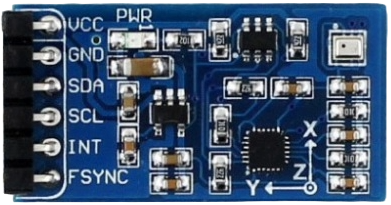
Pin Configuration
The 10 DOF IMU Sensor (C) has the following pinout:
| Pin | Name | Description |
|---|---|---|
| 1 | VCC | Power supply input (3.3V or 5V) |
| 2 | GND | Ground |
| 3 | SCL | I2C clock line |
| 4 | SDA | I2C data line |
| 5 | EDA | Reserved (do not connect) |
| 6 | ECL | Reserved (do not connect) |
Usage Instructions
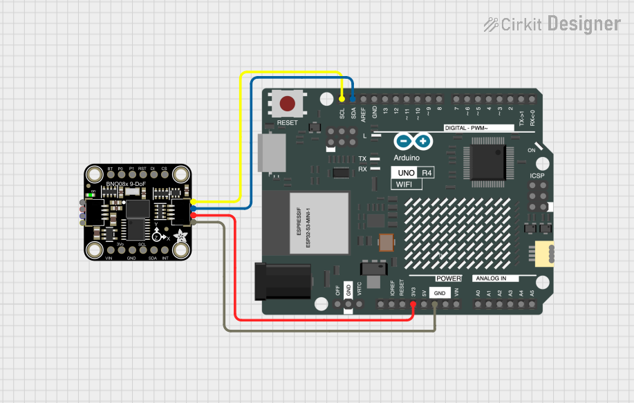
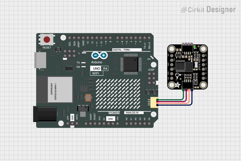
How to Use the Component in a Circuit
- Power Supply: Connect the VCC pin to a 3.3V or 5V power source and the GND pin to ground.
- I2C Communication: Connect the SCL and SDA pins to the corresponding I2C pins on your microcontroller (e.g., Arduino UNO).
- Pull-Up Resistors: Ensure that the I2C lines (SCL and SDA) have pull-up resistors (typically 4.7kΩ) if not already present on the board.
- Address Configuration: The I2C addresses for the sensors are fixed:
- MPU6050: 0x68 or 0x69 (configurable via AD0 pin on MPU6050)
- HMC5883L: 0x1E
- BMP180: 0x77
Important Considerations and Best Practices
- Calibration: Perform sensor calibration (e.g., gyroscope offset, magnetometer hard/soft iron correction) for accurate readings.
- Mounting: Secure the sensor to minimize vibrations and external interference.
- I2C Bus Speed: Use a standard I2C bus speed (100kHz or 400kHz) for reliable communication.
- Power Supply: Ensure a stable power supply to avoid noise in sensor readings.
Example Code for Arduino UNO
Below is an example code snippet to read data from the 10 DOF IMU Sensor (C) using an Arduino UNO:
#include <Wire.h>
#include <Adafruit_Sensor.h>
#include <Adafruit_MPU6050.h>
#include <Adafruit_HMC5883_U.h>
#include <Adafruit_BMP085_U.h>

// Create sensor objects
Adafruit_MPU6050 mpu;
Adafruit_HMC5883_Unified mag = Adafruit_HMC5883_Unified(12345);
Adafruit_BMP085_Unified bmp = Adafruit_BMP085_Unified(10085);

void setup() {
  Serial.begin(9600);
  Wire.begin();

  // Initialize MPU6050
  if (!mpu.begin()) {
    Serial.println("Failed to find MPU6050 chip");
    while (1);
  }
  Serial.println("MPU6050 initialized");

  // Initialize HMC5883L
  if (!mag.begin()) {
    Serial.println("Failed to find HMC5883L chip");
    while (1);
  }
  Serial.println("HMC5883L initialized");

  // Initialize BMP180
  if (!bmp.begin()) {
    Serial.println("Failed to find BMP180 chip");
    while (1);
  }
  Serial.println("BMP180 initialized");
}

void loop() {
  // Read accelerometer and gyroscope data
  sensors_event_t a, g, temp;
  mpu.getEvent(&a, &g, &temp);
  Serial.print("Accel X: "); Serial.print(a.acceleration.x);
  Serial.print(", Y: "); Serial.print(a.acceleration.y);
  Serial.print(", Z: "); Serial.println(a.acceleration.z);

  // Read magnetometer data
  sensors_event_t event;
  mag.getEvent(&event);
  Serial.print("Mag X: "); Serial.print(event.magnetic.x);
  Serial.print(", Y: "); Serial.print(event.magnetic.y);
  Serial.print(", Z: "); Serial.println(event.magnetic.z);

  // Read barometric pressure
  sensors_event_t pressureEvent;
  bmp.getEvent(&pressureEvent);
  Serial.print("Pressure: "); Serial.print(pressureEvent.pressure);
  Serial.println(" hPa");

  delay(1000); // Wait 1 second before next reading
}
Troubleshooting and FAQs
Common Issues
No Data from Sensor:
- Ensure proper wiring and connections.
- Verify the I2C addresses of the sensors.
- Check for pull-up resistors on the I2C lines.
Inaccurate Readings:
- Perform sensor calibration.
- Minimize external interference (e.g., magnetic fields, vibrations).
Communication Errors:
- Ensure the I2C bus speed is compatible with the microcontroller.
- Check for loose or faulty connections.
Solutions and Tips
- Use a logic level shifter if interfacing with a 5V microcontroller and the sensor operates at 3.3V.
- Test each sensor individually to isolate issues.
- Refer to the datasheets of the MPU6050, HMC5883L, and BMP180 for advanced configuration options.
By following this documentation, users can effectively integrate the 10 DOF IMU Sensor (C) into their projects and achieve reliable motion and orientation sensing.