How to Use IMX179 Cam: Examples, Pinouts, and Specs
Introduction
The IMX179 is a high-performance 8-megapixel camera sensor manufactured by Sony. It is widely used in various applications such as smartphones, webcams, and other imaging devices. The sensor is capable of capturing high-resolution images and videos with excellent color accuracy and detail, making it a popular choice for both consumer and industrial markets.
Explore Projects Built with IMX179 Cam
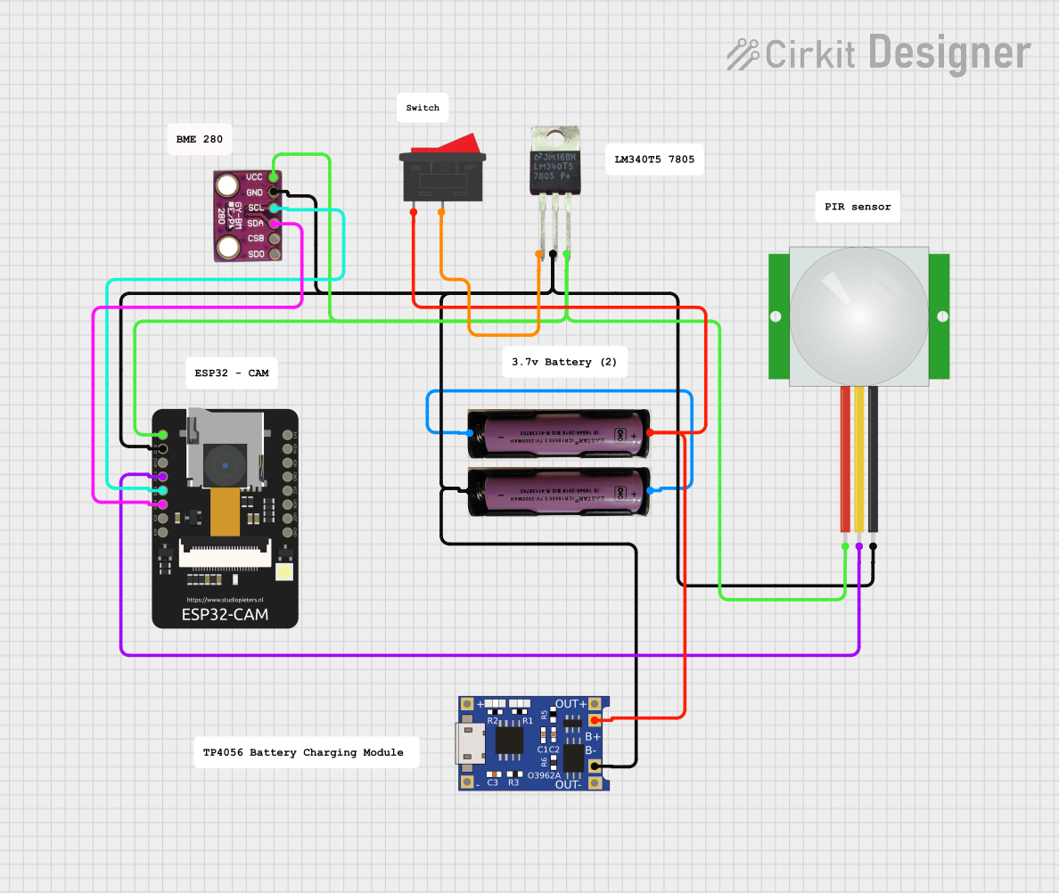
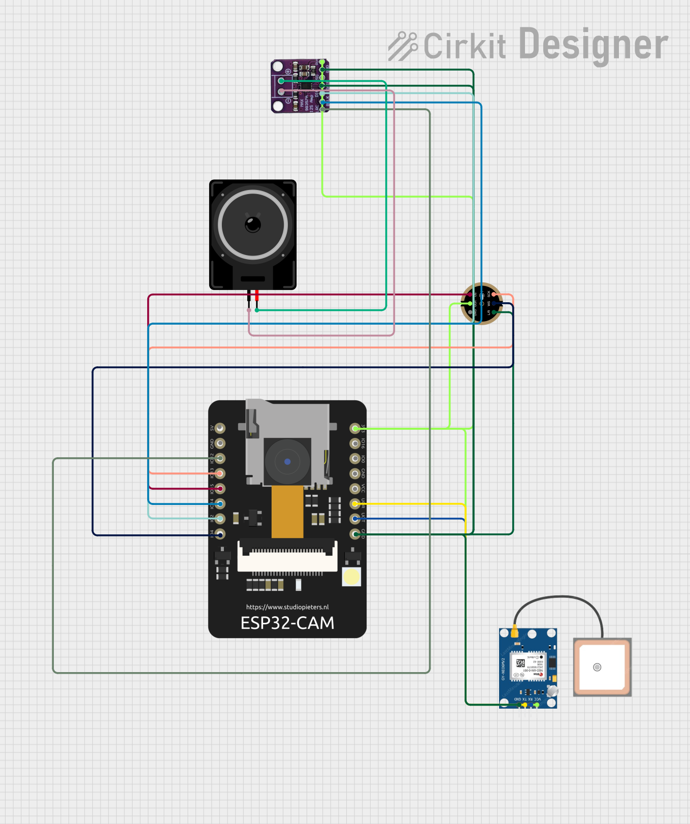


Explore Projects Built with IMX179 Cam
Common Applications and Use Cases
- Mobile phones and tablets
- Webcams for computers
- Security and surveillance cameras
- Drones and aerial photography
- DIY projects and hobbyist applications, including use with Arduino and Raspberry Pi platforms
Technical Specifications
Key Technical Details
- Resolution: 8 Megapixels
- Sensor Type: CMOS
- Optical Format: 1/3.2 inch
- Pixel Size: 1.4 µm x 1.4 µm
- Active Array Size: 3280 x 2464 pixels
- Shutter Type: Rolling shutter
- Frame Rate: Up to 30 fps at full resolution
- Sensitivity: 3300 mV/(lux-sec)
- Dynamic Range: 65.8 dB
- Supply Voltage: 1.5V (analog), 1.2V (digital), 2.8V (I/O)
- Output Interface: MIPI CSI-2
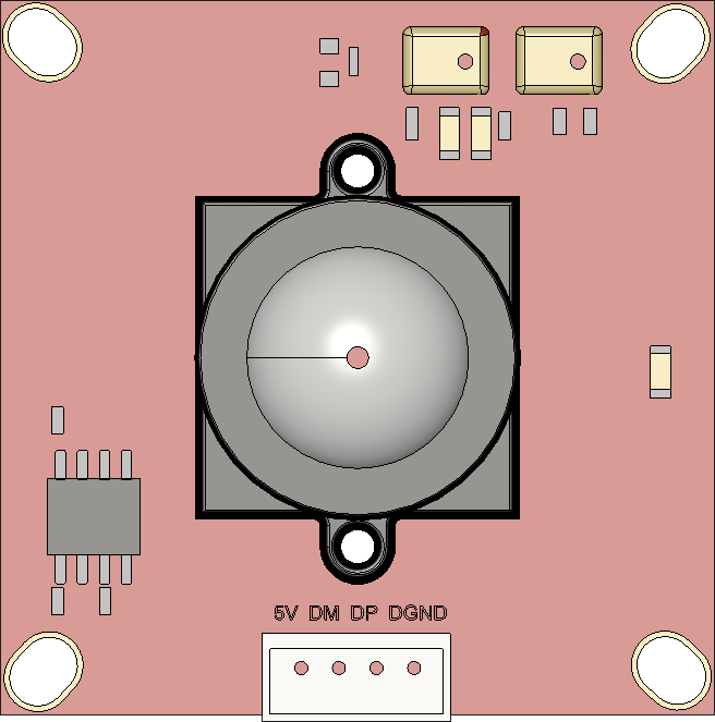
Pin Configuration and Descriptions
| Pin Number | Name | Description |
|---|---|---|
| 1 | VDD | Power supply for digital circuitry |
| 2 | GND | Ground connection |
| 3 | VDDA | Power supply for analog circuitry |
| 4 | VDDIO | Power supply for I/O pins |
| 5-8 | NC | No connection (reserved for future use) |
| 9-12 | D0-D3 | MIPI data lanes for image data output |
| 13 | CLK | MIPI clock lane |
| 14 | GND | Ground connection (shield) |
Usage Instructions
How to Use the Component in a Circuit
- Power Supply: Ensure that the IMX179 is powered correctly with the appropriate voltages to the VDD, VDDA, and VDDIO pins.
- Data Interface: Connect the MIPI CSI-2 data lanes (D0-D3) and clock lane (CLK) to the host processor or controller capable of handling MIPI signals.
- Configuration: Configure the sensor settings such as exposure, gain, and frame rate through the I2C interface (not shown in the pin configuration).
Important Considerations and Best Practices
- ESD Protection: Always handle the IMX179 with proper electrostatic discharge (ESD) precautions.
- Lens Selection: Choose a lens that matches the optical format and desired field of view.
- Temperature: Operate the sensor within the recommended temperature range to prevent damage.
- Firmware: Ensure that the firmware or driver for the host processor supports the IMX179 sensor.
Troubleshooting and FAQs
Common Issues Users Might Face
- No Image Output: Check power supply voltages and MIPI connections. Ensure that the sensor is correctly initialized.
- Poor Image Quality: Adjust the focus of the lens, check for dust or obstructions, and verify sensor settings.
- Intermittent Connection: Inspect the MIPI cable and connectors for any damage or loose connections.
Solutions and Tips for Troubleshooting
- Power Cycling: If the sensor is not responding, try power cycling the device.
- Firmware Updates: Make sure that the latest firmware is installed on the host processor.
- Consult Datasheet: Refer to the IMX179 datasheet for detailed operational guidance and specifications.
FAQs
Q: Can the IMX179 be used with an Arduino UNO? A: The IMX179 requires a high-speed MIPI interface, which is not natively supported by Arduino UNO. An additional MIPI to parallel converter or a more capable microcontroller with MIPI support is needed.
Q: What is the maximum video resolution and frame rate? A: The IMX179 can capture video at a maximum resolution of 3280 x 2464 pixels at 30 frames per second.
Q: Does the IMX179 support still image capture? A: Yes, the IMX179 can capture still images at full resolution.
Q: Is there a recommended operating temperature for the IMX179? A: The recommended operating temperature range for the IMX179 is typically from -30°C to +70°C. Always refer to the manufacturer's datasheet for precise information.
Q: Where can I find drivers for the IMX179? A: Drivers for the IMX179 can typically be obtained from the manufacturer or the supplier of the host processor or development board you are using.
Example Code for Arduino UNO
Due to the complexity of interfacing the IMX179 with an Arduino UNO, example code is not provided in this documentation. Users looking to integrate the IMX179 with an Arduino platform should consider using a shield or module designed to interface with high-speed camera sensors, and refer to the documentation provided with that hardware for example code and usage instructions.