
How to Use Peppermill Power Board: Examples, Pinouts, and Specs
 Design with Peppermill Power Board in Cirkit Designer
Introduction
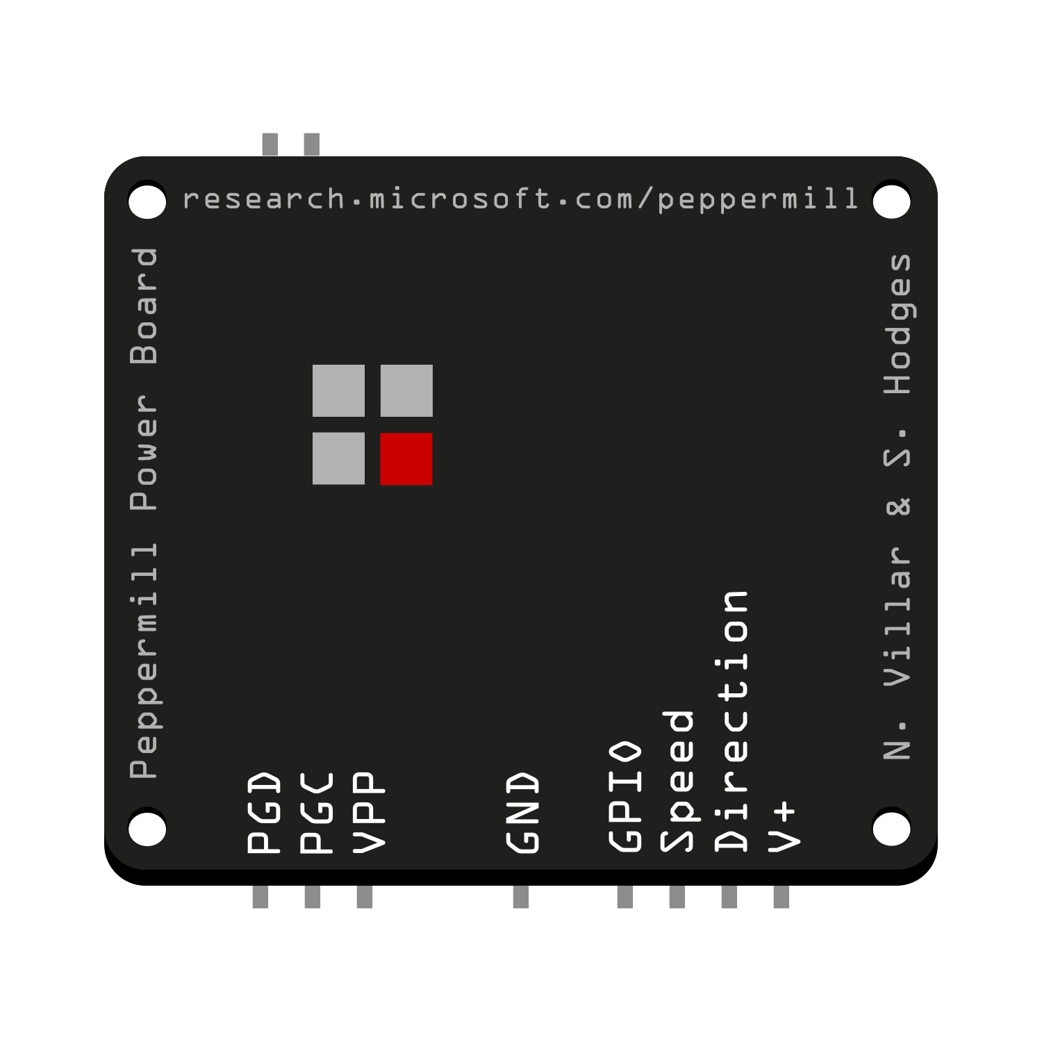
The Peppermill Power Board is a specialized electronic component designed by Microsoft Research to provide reliable power delivery for electric pepper mills. It ensures the proper voltage and current levels required to operate the motor and grinding mechanism efficiently. This compact and robust power board is ideal for small appliances, particularly those requiring consistent motor performance in compact spaces.
Explore Projects Built with Peppermill Power Board
 Open Project in Cirkit Designer
 Open Project in Cirkit Designer
 Open Project in Cirkit Designer
 Open Project in Cirkit Designer
Explore Projects Built with Peppermill Power Board
Open Project in Cirkit DesignerOpen Project in Cirkit DesignerOpen Project in Cirkit DesignerOpen Project in Cirkit DesignerCommon Applications and Use Cases
- Electric pepper mills and grinders
- Small motorized kitchen appliances
- Low-power motor control applications
- Prototyping for compact motorized devices
Technical Specifications
The following table outlines the key technical details of the Peppermill Power Board:
| Parameter | Value |
|---|---|
| Manufacturer | Microsoft Research |
| Part ID | Peppermill Power Board |
| Input Voltage Range | 3.0V - 6.0V DC |
| Output Voltage | 3.3V DC |
| Maximum Output Current | 1.5A |
| Power Efficiency | 85% (typical) |
| Dimensions | 25mm x 15mm x 5mm |
| Operating Temperature | -10°C to 60°C |
| Weight | 5 grams |
Pin Configuration and Descriptions
The Peppermill Power Board features a simple pinout for easy integration into circuits. The pin configuration is as follows:
| Pin | Name | Description |
|---|---|---|
| 1 | VIN | Input voltage (3.0V - 6.0V DC) |
| 2 | GND | Ground connection |
| 3 | VOUT | Regulated output voltage (3.3V DC) |
| 4 | ENABLE | Enable pin (active HIGH to enable the power board) |
Usage Instructions
How to Use the Component in a Circuit
- Power Input: Connect the VIN pin to a DC power source within the range of 3.0V to 6.0V. Ensure the power source can supply sufficient current for the motor and the board (at least 1.5A).
- Ground Connection: Connect the GND pin to the ground of your circuit.
- Output Voltage: Use the VOUT pin to power the motor or other components requiring 3.3V DC.
- Enable Pin: To activate the power board, connect the ENABLE pin to a HIGH signal (e.g., 3.3V). To disable the board, set the ENABLE pin to LOW or leave it unconnected.
Important Considerations and Best Practices
- Input Voltage: Ensure the input voltage does not exceed 6.0V to avoid damaging the board.
- Heat Dissipation: Although the board is efficient, prolonged operation at high currents may generate heat. Ensure adequate ventilation or heat sinking if necessary.
- Polarity: Double-check the polarity of the input voltage to prevent damage to the board.
- Motor Compatibility: Verify that the motor's voltage and current requirements match the board's output specifications.
Example: Connecting to an Arduino UNO
The Peppermill Power Board can be used to power small motors controlled by an Arduino UNO. Below is an example circuit and code to control a motor using the board and an Arduino:
Circuit Connections
- Connect the VIN pin of the power board to a 5V DC power source.
- Connect the GND pin of the power board to the Arduino's GND.
- Connect the VOUT pin of the power board to the motor's positive terminal.
- Connect the motor's negative terminal to the Arduino's GND.
- Connect the ENABLE pin of the power board to a digital pin on the Arduino (e.g., pin 7).
Arduino Code
// Define the ENABLE pin connected to the Peppermill Power Board
const int enablePin = 7;

void setup() {
  // Set the ENABLE pin as an output
  pinMode(enablePin, OUTPUT);

  // Enable the power board to power the motor
  digitalWrite(enablePin, HIGH);
}

void loop() {
  // The motor will remain powered as long as the ENABLE pin is HIGH
  // Add motor control logic here if needed
}
Troubleshooting and FAQs
Common Issues and Solutions
The motor does not start:
- Ensure the ENABLE pin is set to HIGH.
- Verify the input voltage is within the specified range (3.0V - 6.0V).
- Check all connections for proper polarity and secure contact.
The board overheats:
- Ensure the motor's current draw does not exceed 1.5A.
- Provide adequate ventilation or a heat sink if operating at high currents for extended periods.
No output voltage on VOUT:
- Confirm that the ENABLE pin is connected to a HIGH signal.
- Check the input voltage and ensure it is within the specified range.
The board is damaged after connection:
- Verify that the input voltage polarity is correct.
- Ensure the input voltage does not exceed 6.0V.
FAQs
Q: Can the Peppermill Power Board be used with a 12V power source?
A: No, the maximum input voltage is 6.0V. Using a 12V power source will damage the board.
Q: Is the board compatible with other microcontrollers besides Arduino?
A: Yes, the board can be used with any microcontroller that can provide a HIGH signal (e.g., 3.3V or 5V) to the ENABLE pin.
Q: Can I use the board to power devices other than motors?
A: Yes, as long as the device operates at 3.3V DC and does not exceed 1.5A of current.
Q: Does the board have reverse polarity protection?
A: No, the board does not include reverse polarity protection. Always double-check the polarity of your connections.