How to Use 24V Power Cord: Examples, Pinouts, and Specs
Introduction
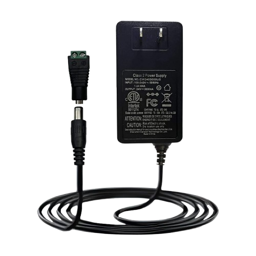
The 24V Power Cord is a cable designed to connect electrical devices to a 24V power supply, ensuring they receive the necessary voltage for proper operation. This component is essential in a wide range of applications, including industrial equipment, LED lighting systems, and various electronic devices requiring a stable 24V DC input. Its robust design ensures reliable power delivery and durability in demanding environments.
Explore Projects Built with 24V Power Cord

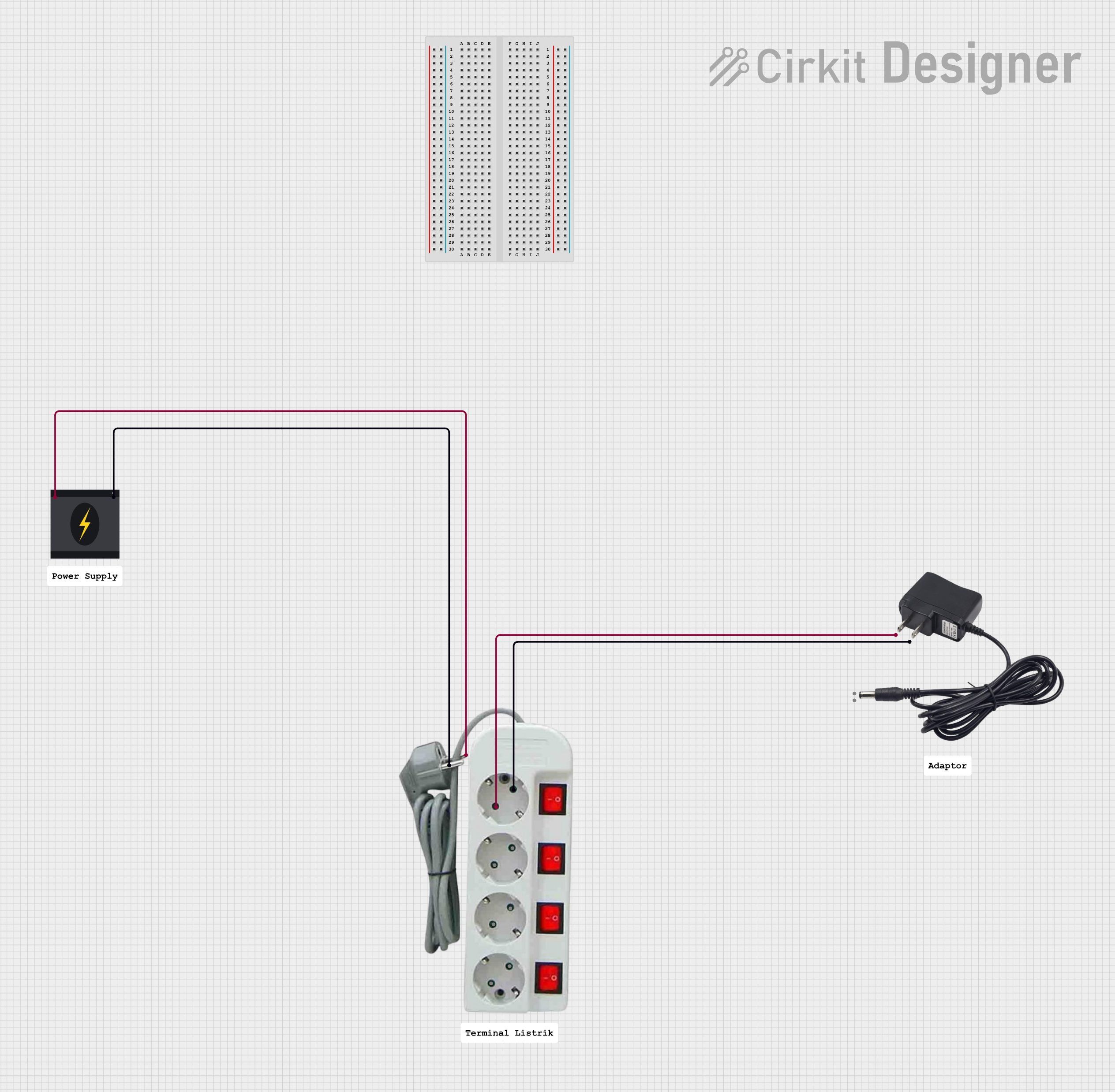


Explore Projects Built with 24V Power Cord
Common Applications:
- Industrial machinery and automation systems
- LED lighting installations
- 24V DC-powered electronic devices
- Robotics and motor controllers
- Laboratory equipment and test setups
Technical Specifications
The 24V Power Cord is available in various configurations to suit different applications. Below are the general technical specifications:
| Parameter | Specification |
|---|---|
| Voltage Rating | 24V DC |
| Current Rating | Typically up to 10A (varies by model) |
| Connector Type | Barrel jack, spade terminals, or bare wire |
| Cable Length | 1m to 5m (varies by model) |
| Wire Gauge | 18 AWG to 14 AWG |
| Insulation Material | PVC or silicone |
| Operating Temperature | -20°C to 80°C |
Pin Configuration and Descriptions
For 24V Power Cords with barrel connectors, the pin configuration is as follows:
| Pin | Description |
|---|---|
| Center | Positive terminal (+24V) |
| Outer | Negative terminal (GND) |
For bare wire configurations:
- Red wire: Positive terminal (+24V)
- Black wire: Negative terminal (GND)
Usage Instructions
How to Use the 24V Power Cord in a Circuit
- Verify Compatibility: Ensure the device you are powering is designed to operate at 24V DC and does not exceed the current rating of the power cord.
- Connect to Power Supply:
- For barrel connectors: Insert the connector into the device's power input jack.
- For bare wire configurations: Connect the red wire to the positive terminal and the black wire to the negative terminal of the power supply.
- Secure Connections: Ensure all connections are tight and insulated to prevent short circuits.
- Power On: Turn on the power supply and verify that the device operates correctly.
Important Considerations and Best Practices
- Polarity: Always double-check the polarity of the connections to avoid damaging the device.
- Current Rating: Ensure the power cord's current rating matches or exceeds the device's current requirements.
- Cable Length: Use the shortest cable length possible to minimize voltage drop.
- Environment: Avoid exposing the cord to extreme temperatures, moisture, or physical damage.
Example: Connecting to an Arduino UNO
While the Arduino UNO typically operates at 5V, it can be powered via a 24V power supply using a step-down voltage regulator. Below is an example of how to integrate the 24V Power Cord into such a setup:
// Example code for Arduino UNO powered via a 24V power supply
// Ensure a step-down regulator is used to convert 24V to 5V for the Arduino

void setup() {
  // Initialize serial communication for debugging
  Serial.begin(9600);
  Serial.println("Arduino powered via 24V supply with step-down regulator.");
}

void loop() {
  // Example loop code
  Serial.println("System running...");
  delay(1000); // Wait for 1 second
}
Troubleshooting and FAQs
Common Issues
Device Does Not Power On:
- Cause: Incorrect polarity or loose connections.
- Solution: Verify the polarity and ensure all connections are secure.
Overheating of the Power Cord:
- Cause: Exceeding the current rating of the cord.
- Solution: Use a power cord with a higher current rating.
Voltage Drop Across the Cord:
- Cause: Excessive cable length or insufficient wire gauge.
- Solution: Use a shorter cable or one with a lower gauge (thicker wire).
Intermittent Power Delivery:
- Cause: Damaged insulation or internal wire breakage.
- Solution: Inspect the cord for damage and replace if necessary.
FAQs
Q: Can I use the 24V Power Cord for AC power?
A: No, the 24V Power Cord is designed specifically for DC power applications. Using it for AC power may result in damage or unsafe operation.
Q: What happens if I reverse the polarity?
A: Reversing the polarity can damage the connected device. Always verify the polarity before powering on.
Q: Can I extend the length of the power cord?
A: Yes, but ensure the extended length does not cause significant voltage drop. Use a thicker wire gauge if extending the cable.
Q: Is the 24V Power Cord waterproof?
A: Most standard 24V Power Cords are not waterproof. For outdoor or wet environments, use a cord with appropriate waterproofing or insulation.