How to Use Rotary Encoder incremental type side mount: Examples, Pinouts, and Specs
Introduction
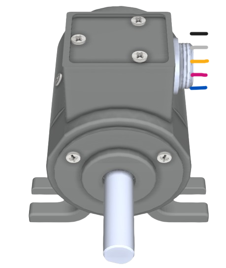
A rotary encoder, specifically the incremental type with a side mount, is an essential component in the realm of electronics for precise position tracking. It is an electromechanical device that translates the angular position or motion of a shaft into an analog or digital output signal. This type of encoder is particularly useful in applications that require accurate monitoring of rotational movement, such as in robotics, CNC machines, and various industrial control systems. The side mount design allows for convenient installation on the side of equipment, making it easily accessible for maintenance and integration.
Explore Projects Built with Rotary Encoder incremental type side mount

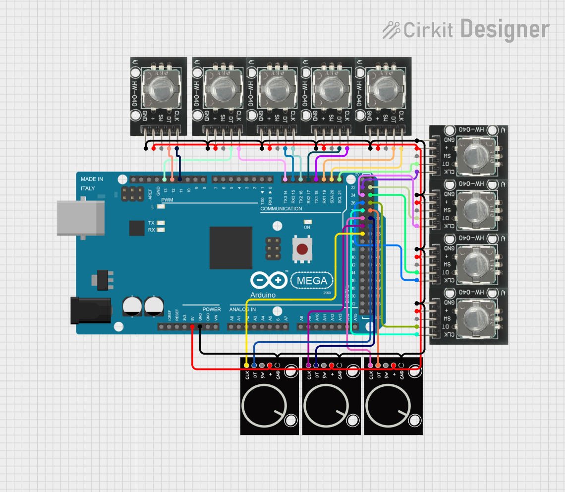
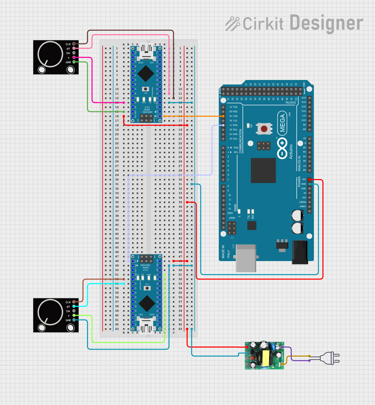
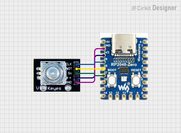
Explore Projects Built with Rotary Encoder incremental type side mount
Technical Specifications
General Features
- Type: Incremental Rotary Encoder
- Mounting Style: Side Mount
- Output Signal: Digital Quadrature (A and B phase)
- Resolution: Typically ranges from 100 to 10,000 pulses per revolution (PPR)
- Supply Voltage: 5V DC (typical for use with microcontrollers like Arduino)
- Maximum Rotational Speed: Specified in RPM, varies by model
- Operating Temperature Range: -20°C to +70°C (varies by model)
Pin Configuration and Descriptions
| Pin Number | Description | Notes |
|---|---|---|
| 1 | Ground (GND) | Connect to system ground |
| 2 | Supply Voltage (Vcc) | Typically 5V DC |
| 3 | Output A | Quadrature output A |
| 4 | Output B | Quadrature output B |
| 5 | Index (Optional) | Pulse per revolution (if present) |
Note: The pin configuration may vary slightly depending on the manufacturer. Always refer to the datasheet of the specific model you are using.
Usage Instructions
Integration into a Circuit
- Power Connections: Connect the Vcc pin to a 5V supply, and the GND pin to the common ground in your circuit.
- Output Signals: Connect the Output A and Output B pins to two digital input pins on your microcontroller.
- Index Signal (if available): Connect the Index pin to another digital input pin if you require a reference signal for each revolution.
Best Practices
- Use pull-up resistors on the output lines to ensure reliable signal levels, especially in noisy environments.
- Implement hardware or software debouncing to counteract signal chatter.
- Shield the encoder and wiring if used in an environment with high electromagnetic interference (EMI).
Example Code for Arduino UNO
// Define the connections to the Arduino
const int pinA = 2; // Output A
const int pinB = 3; // Output B

// Variables to hold the current and last encoder state
volatile int encoderPos = 0;
int lastEncoded = 0;

void setup() {
  pinMode(pinA, INPUT);
  pinMode(pinB, INPUT);
  digitalWrite(pinA, HIGH); // Enable pull-up resistor
  digitalWrite(pinB, HIGH); // Enable pull-up resistor
  attachInterrupt(digitalPinToInterrupt(pinA), updateEncoder, CHANGE);
  attachInterrupt(digitalPinToInterrupt(pinB), updateEncoder, CHANGE);
  Serial.begin(9600);
}

void loop() {
  // The main loop can handle other tasks while the encoder position is updated
  // via interrupts.
  Serial.println(encoderPos);
  delay(1000);
}

void updateEncoder() {
  // Function to be called by the interrupt service routine
  int MSB = digitalRead(pinA); // MSB = most significant bit
  int LSB = digitalRead(pinB); // LSB = least significant bit

  int encoded = (MSB << 1) | LSB; // Converting the 2 pin value to single number
  int sum = (lastEncoded << 2) | encoded; // Adding it to the previous encoded value

  if(sum == 0b1101 || sum == 0b0100 || sum == 0b0010 || sum == 0b1011) encoderPos++;
  if(sum == 0b1110 || sum == 0b0111 || sum == 0b0001 || sum == 0b1000) encoderPos--;

  lastEncoded = encoded; // Store this value for next time
}
Note: The above code uses interrupts to monitor the state changes of the encoder outputs, which allows the main program to run without waiting for the encoder to turn. This is a simple example and does not handle the index signal.
Troubleshooting and FAQs
Common Issues
- Erratic Signals: If the encoder outputs erratic signals, ensure that the pull-up resistors are in place and that there is no EMI interference.
- No Output: Check the power supply connections and verify that the encoder is receiving the correct voltage.
- Inaccurate Positioning: Make sure that the encoder is mounted correctly and that there is no mechanical play or obstruction.
FAQs
Q: Can I use this encoder with a 3.3V system? A: Yes, but ensure that the encoder is compatible with 3.3V logic levels. Check the datasheet for voltage ratings.
Q: How can I increase the resolution of my encoder readings? A: You can increase resolution by using an encoder with a higher PPR specification or by implementing software interpolation techniques.
Q: What is the purpose of the index signal? A: The index signal provides a single pulse per revolution, which can be used as a reference point for absolute positioning.
For further assistance, consult the manufacturer's datasheet and technical support resources.