How to Use Water Sensor: Examples, Pinouts, and Specs
Introduction
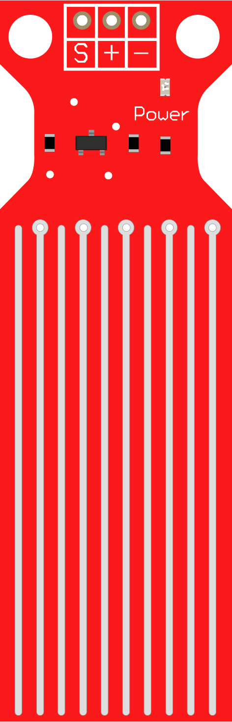
The Water Sensor is a device designed to detect the presence of water or measure moisture levels in various environments. It is commonly used in applications such as leak detection, flood monitoring, soil moisture measurement, and smart home automation systems. The sensor operates by detecting changes in conductivity when water comes into contact with its exposed terminals.
Explore Projects Built with Water Sensor
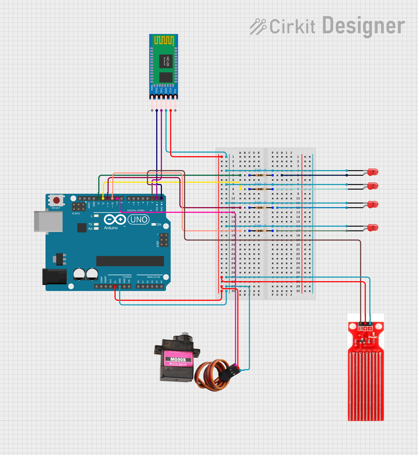
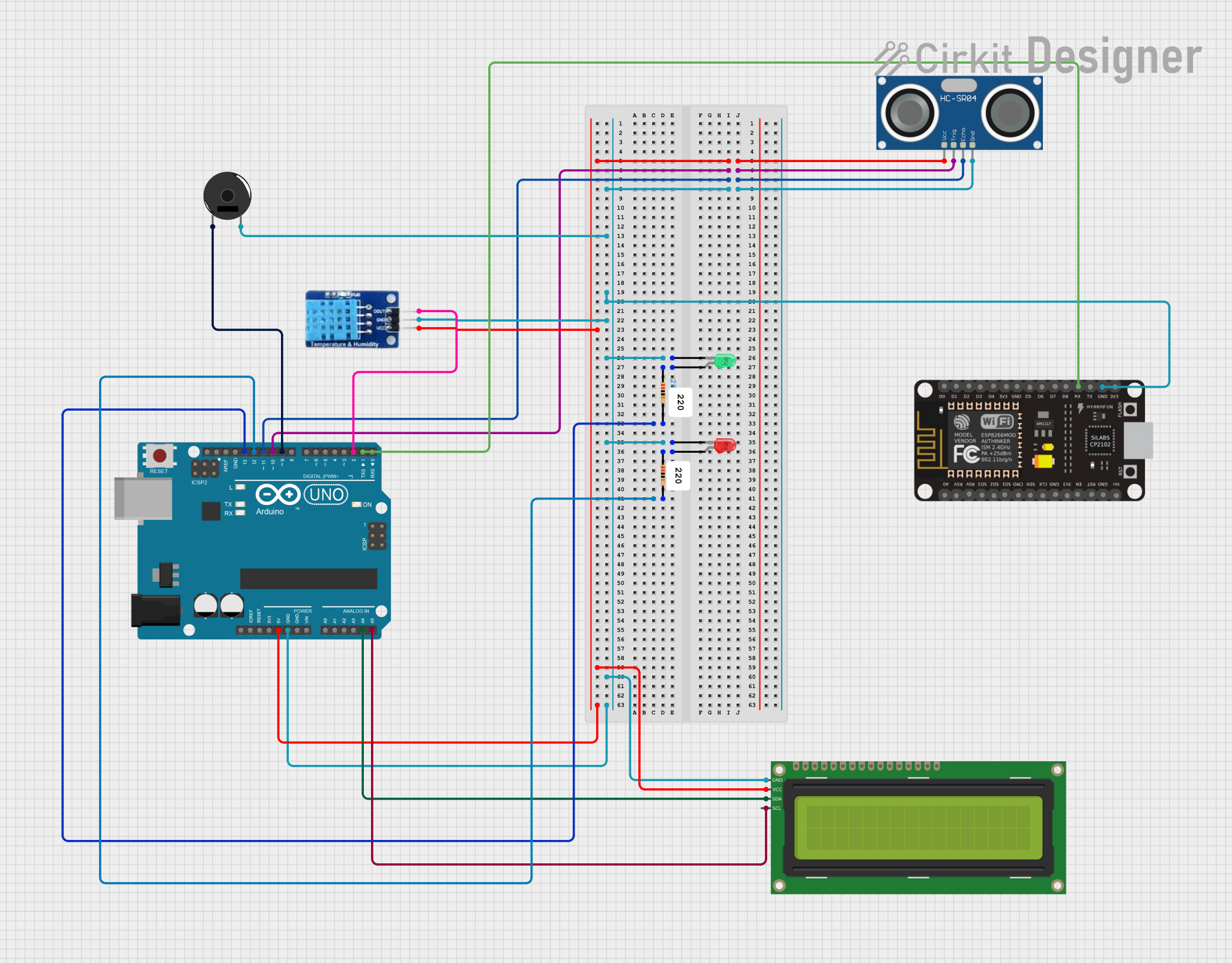
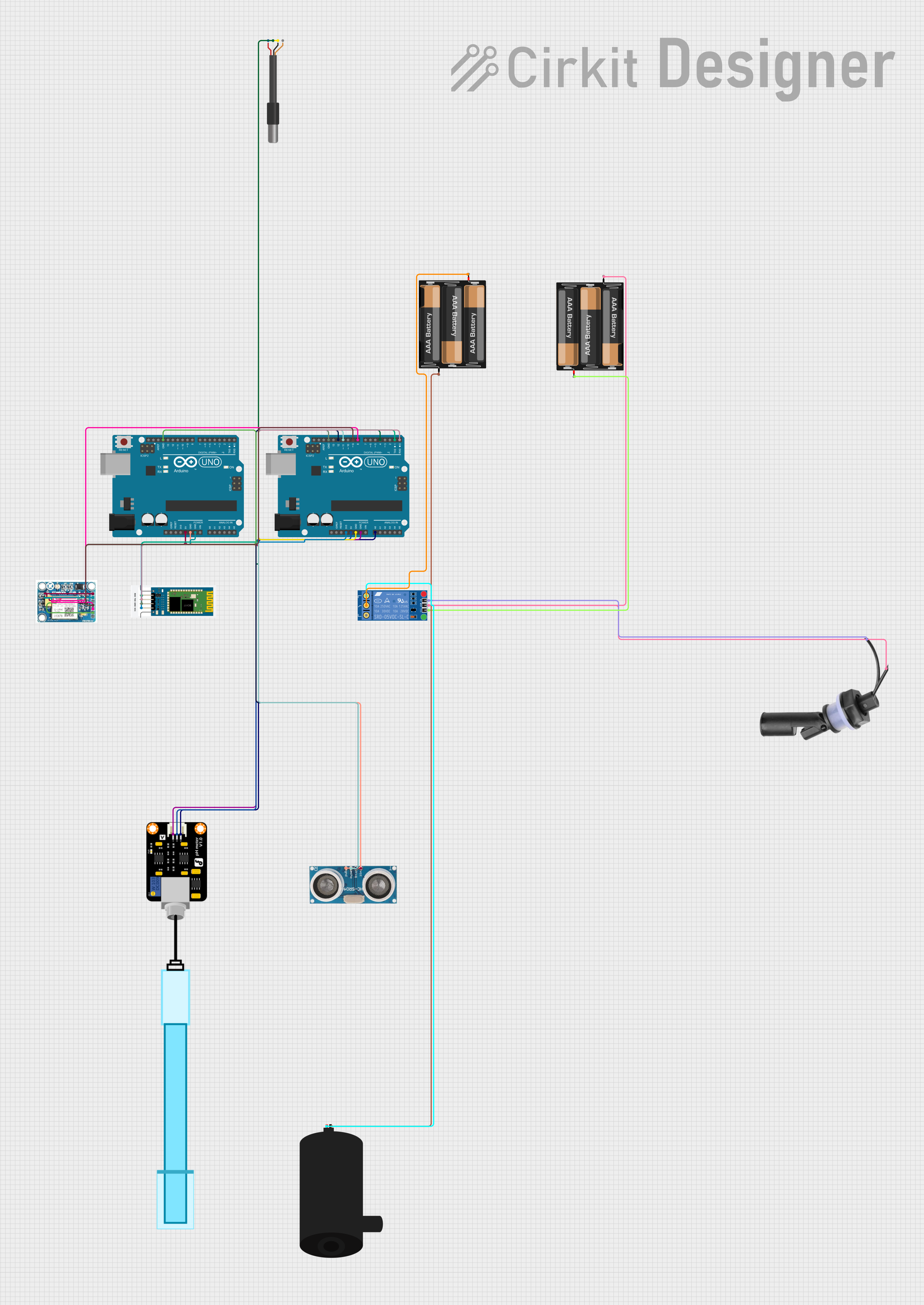
Explore Projects Built with Water Sensor
Technical Specifications
- Operating Voltage: 3.3V to 5V
- Operating Current: < 20mA
- Output Type: Analog and Digital
- Detection Area: Exposed PCB with conductive traces
- Dimensions: Typically 20mm x 60mm (varies by model)
- Interface: 3-pin connector (VCC, GND, Signal)
Pin Configuration and Descriptions
| Pin Name | Description |
|---|---|
| VCC | Power supply pin. Connect to 3.3V or 5V depending on your system voltage. |
| GND | Ground pin. Connect to the ground of your circuit. |
| Signal | Output pin. Provides an analog voltage proportional to water presence or a |
| digital HIGH/LOW signal depending on the sensor's configuration. |
Usage Instructions
Connecting the Water Sensor
- Power Supply: Connect the VCC pin to a 3.3V or 5V power source, depending on your system.
- Ground: Connect the GND pin to the ground of your circuit.
- Signal Output:
- For analog output, connect the Signal pin to an analog input pin on your microcontroller.
- For digital output, connect the Signal pin to a digital input pin on your microcontroller.
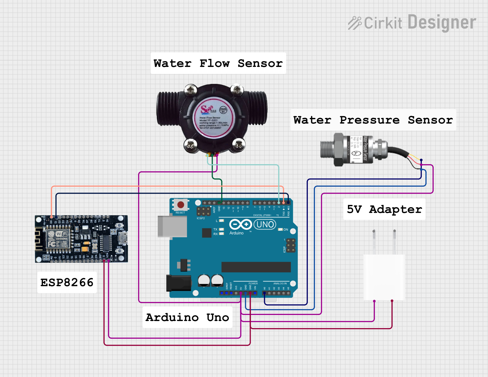
Example Circuit with Arduino UNO
Below is an example of how to connect the Water Sensor to an Arduino UNO:
- VCC → 5V pin on Arduino
- GND → GND pin on Arduino
- Signal → A0 (analog input pin) on Arduino
Sample Arduino Code
// Water Sensor Example Code
// This code reads the analog value from the water sensor and prints it to the Serial Monitor.

const int waterSensorPin = A0; // Define the analog pin connected to the sensor
int sensorValue = 0;          // Variable to store the sensor reading

void setup() {
  Serial.begin(9600); // Initialize serial communication at 9600 baud
}

void loop() {
  sensorValue = analogRead(waterSensorPin); // Read the analog value from the sensor
  Serial.print("Water Sensor Value: ");
  Serial.println(sensorValue); // Print the sensor value to the Serial Monitor

  // Add a small delay to avoid flooding the Serial Monitor
  delay(500);
}
Important Considerations and Best Practices
- Avoid Prolonged Exposure: Prolonged exposure to water can corrode the sensor's conductive traces. Use the sensor for intermittent measurements or ensure proper maintenance.
- Voltage Compatibility: Ensure the sensor's operating voltage matches your microcontroller's input voltage to avoid damage.
- Environmental Factors: The sensor is not waterproof. Avoid submerging the entire sensor module in water.
- Calibration: For precise measurements, calibrate the sensor to account for environmental factors such as temperature and water conductivity.
Troubleshooting and FAQs
Common Issues
No Output or Incorrect Readings:
- Ensure the sensor is properly connected to the power supply and ground.
- Verify that the Signal pin is connected to the correct input pin on your microcontroller.
- Check for corrosion or damage on the sensor's conductive traces.
Fluctuating Readings:
- Ensure the sensor is not exposed to electrical noise or interference.
- Stabilize the sensor's output by adding a capacitor (e.g., 0.1µF) between the Signal pin and GND.
Sensor Not Detecting Water:
- Verify that the water is making proper contact with the sensor's conductive traces.
- Check the sensor's sensitivity and adjust the threshold in your code if using digital output.
FAQs
Q: Can the Water Sensor be used to measure the water level?
A: The Water Sensor is primarily designed to detect the presence of water, not to measure water levels. For water level measurement, consider using a dedicated water level sensor.
Q: Is the Water Sensor waterproof?
A: No, the sensor is not waterproof. Only the exposed conductive traces are designed to come into contact with water. Avoid submerging the entire module.
Q: How can I increase the sensor's lifespan?
A: Minimize prolonged exposure to water, clean the sensor regularly to prevent corrosion, and store it in a dry environment when not in use.
Q: Can I use the Water Sensor with a 3.3V microcontroller?
A: Yes, the sensor is compatible with both 3.3V and 5V systems. Ensure the VCC pin is connected to the appropriate voltage source.