How to Use EOCR: Examples, Pinouts, and Specs
Introduction
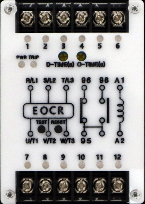
The Electronic Overcurrent Relay (EOCR), manufactured by Cirkit (Part ID: EOCR), is a protective device designed to monitor and safeguard electrical circuits from overcurrent conditions. By detecting abnormal current levels, the EOCR disconnects the circuit to prevent damage to equipment, reduce downtime, and enhance operational safety. This device is widely used in industrial and commercial applications where reliable circuit protection is critical.
Explore Projects Built with EOCR
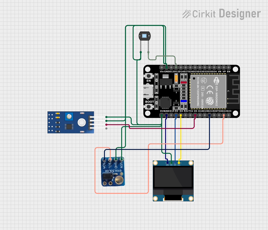
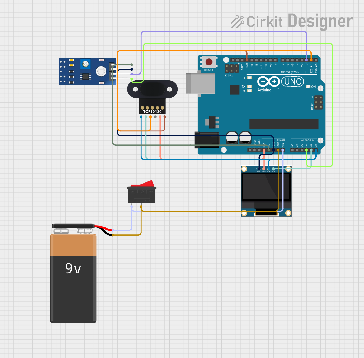
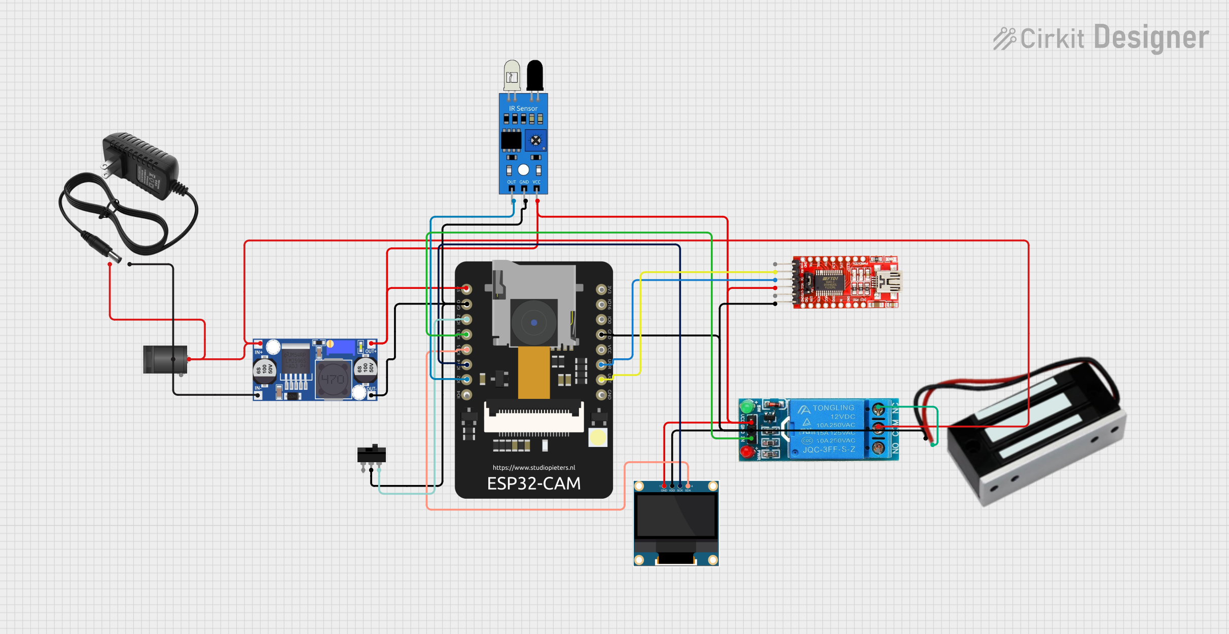
Explore Projects Built with EOCR
Common Applications and Use Cases
- Protection of motors and transformers from overcurrent and short circuits.
- Industrial automation systems requiring precise current monitoring.
- Electrical panels in commercial buildings.
- Renewable energy systems, such as solar inverters, to prevent overcurrent damage.
- HVAC systems and other high-power electrical equipment.
Technical Specifications
Key Technical Details
| Parameter | Specification |
|---|---|
| Operating Voltage Range | 24V AC/DC to 240V AC/DC |
| Current Range | 0.5A to 60A (adjustable) |
| Trip Time Delay | 0.1 to 30 seconds (adjustable) |
| Frequency Range | 50Hz / 60Hz |
| Contact Configuration | 1 NO (Normally Open) + 1 NC (Normally Closed) |
| Power Consumption | < 5W |
| Operating Temperature | -20°C to +60°C |
| Mounting Type | DIN Rail or Panel Mount |
| Dimensions | 90mm x 70mm x 60mm |
| Certifications | CE, UL, RoHS |
Pin Configuration and Descriptions
The EOCR has a terminal block for wiring connections. Below is the pin configuration:
| Pin Number | Label | Description |
|---|---|---|
| 1 | L1 | Line input (Phase 1) |
| 2 | L2 | Line input (Phase 2) |
| 3 | L3 | Line input (Phase 3) |
| 4 | T1 | Load output (Phase 1) |
| 5 | T2 | Load output (Phase 2) |
| 6 | T3 | Load output (Phase 3) |
| 7 | NC | Normally Closed contact for alarm circuit |
| 8 | NO | Normally Open contact for alarm circuit |
| 9 | COM | Common terminal for alarm circuit |
| 10 | GND | Ground connection |
Usage Instructions
How to Use the EOCR in a Circuit
Wiring the EOCR:
- Connect the three-phase input lines (L1, L2, L3) to pins 1, 2, and 3, respectively.
- Connect the load (e.g., motor) to the output terminals (T1, T2, T3) on pins 4, 5, and 6.
- For alarm or control circuits, use the NC, NO, and COM terminals (pins 7, 8, and 9) as required.
- Ensure the ground (GND) is properly connected to pin 10.
Adjusting Settings:
- Use the rotary dials or digital interface (depending on the model) to set the desired current range and trip time delay.
- Verify the settings match the load requirements to avoid nuisance tripping.
Testing the EOCR:
- After installation, simulate an overcurrent condition to ensure the relay trips and disconnects the circuit as expected.
- Check the alarm circuit functionality by monitoring the NC and NO contacts.
Integration with Microcontrollers:
- The EOCR can be connected to a microcontroller (e.g., Arduino UNO) for monitoring and control.
- Use the NO or NC contact to send a digital signal to the microcontroller when an overcurrent condition is detected.
Arduino UNO Example Code
Below is an example of how to interface the EOCR with an Arduino UNO to monitor overcurrent conditions:
// Define the pin connected to the EOCR NO (Normally Open) contact
const int eocrPin = 2;  // Digital pin 2 on Arduino UNO

void setup() {
  pinMode(eocrPin, INPUT_PULLUP);  // Set the pin as input with pull-up resistor
  Serial.begin(9600);             // Initialize serial communication
}

void loop() {
  int eocrState = digitalRead(eocrPin);  // Read the state of the EOCR contact

  if (eocrState == LOW) {
    // EOCR has detected an overcurrent condition
    Serial.println("Overcurrent detected! Circuit disconnected.");
  } else {
    // Normal operation
    Serial.println("Circuit operating normally.");
  }

  delay(1000);  // Wait for 1 second before checking again
}
Important Considerations and Best Practices
- Ensure the EOCR's current range and trip time delay are properly configured for the specific application.
- Regularly inspect the wiring and connections to prevent loose contacts or corrosion.
- Avoid exposing the EOCR to extreme temperatures or moisture to maintain reliability.
- Use appropriate fuses or circuit breakers in conjunction with the EOCR for added protection.
Troubleshooting and FAQs
Common Issues and Solutions
EOCR Does Not Trip During Overcurrent:
- Cause: Incorrect current range or trip time delay settings.
- Solution: Verify and adjust the settings to match the load requirements.
Frequent Nuisance Tripping:
- Cause: Trip time delay set too low or load inrush current exceeding the set range.
- Solution: Increase the trip time delay or adjust the current range to accommodate inrush current.
Alarm Circuit Not Functioning:
- Cause: Incorrect wiring of NC, NO, or COM terminals.
- Solution: Check the wiring and ensure proper connections to the alarm circuit.
No Power to the EOCR:
- Cause: Faulty power supply or loose connections.
- Solution: Verify the power supply voltage and inspect the wiring for loose or damaged connections.
FAQs
Q1: Can the EOCR be used with single-phase systems?
A1: Yes, the EOCR can be used with single-phase systems by connecting only one phase (L1 and T1) and leaving the other terminals unconnected.
Q2: What happens if the EOCR detects an overcurrent condition?
A2: The EOCR will trip and disconnect the load from the power supply. Additionally, the alarm circuit will activate to indicate the fault.
Q3: Is the EOCR compatible with renewable energy systems?
A3: Yes, the EOCR can be used in renewable energy systems, such as solar inverters, to protect against overcurrent conditions.
Q4: How often should the EOCR be tested?
A4: It is recommended to test the EOCR at least once every six months to ensure proper functionality.