How to Use Toggle Switch: Examples, Pinouts, and Specs
Introduction
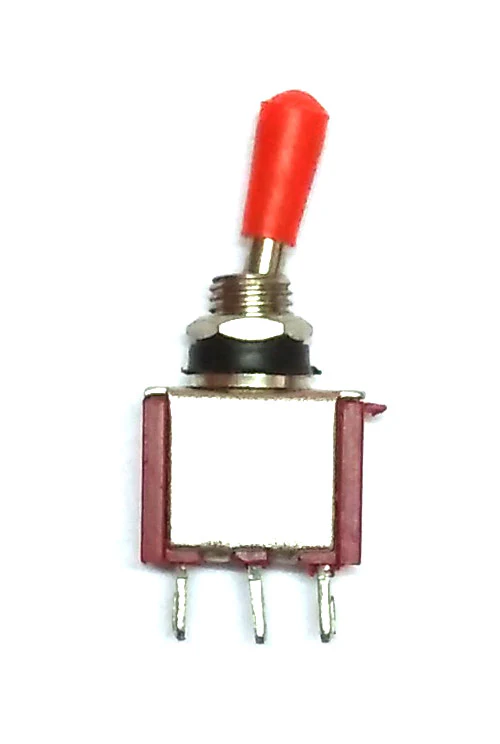
A toggle switch is a fundamental electrical component widely used to control the flow of electricity in a circuit. It operates by manually flipping a lever to alternate between an open (off) and closed (on) state, allowing or interrupting the current flow. Toggle switches are commonly found in various applications, from household lighting to industrial machinery, and even in consumer electronics where manual control is required.
Explore Projects Built with Toggle Switch

Explore Projects Built with Toggle Switch
Technical Specifications
Toggle switches come in various sizes and ratings, tailored to different applications. Below are the general technical specifications you might find for a standard toggle switch:
- Voltage Rating: The maximum voltage the switch can handle, typically ranging from 120V to 250V for household switches and lower for electronics.
- Current Rating: The maximum current the switch can carry, often between 2A to 20A.
- Contact Configuration: Single Pole Single Throw (SPST), Single Pole Double Throw (SPDT), Double Pole Single Throw (DPST), or Double Pole Double Throw (DPDT).
- Terminal Type: Screw, solder lug, or quick-connect.
- Actuator: The part of the switch that is moved to change its position, usually a lever or bat.
- Mechanical Life: The number of cycles the switch can operate without mechanical failure.
Pin Configuration and Descriptions
For a simple SPST toggle switch, the pin configuration is straightforward:
| Pin Number | Description |
|---|---|
| 1 | Common terminal (C) |
| 2 | Normally Open (NO) |
For an SPDT toggle switch, the configuration includes an additional terminal:
| Pin Number | Description |
|---|---|
| 1 | Common terminal (C) |
| 2 | Normally Open (NO) |
| 3 | Normally Closed (NC) |
Usage Instructions
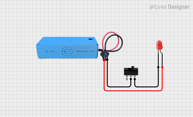
Incorporating a Toggle Switch into a Circuit
- Identify the Type of Toggle Switch: Determine whether you need an SPST, SPDT, DPST, or DPDT switch based on your circuit requirements.
- Power Off the Circuit: Ensure that the power supply to the circuit is turned off before installing the switch to prevent electric shock or damage.
- Connect the Terminals: For an SPST switch, connect the power line to the common terminal (C) and the load to the Normally Open (NO) terminal. For an SPDT switch, you can also connect a second load to the Normally Closed (NC) terminal if desired.
- Secure the Switch: Mount the switch onto the panel or enclosure, ensuring it is firmly in place.
- Test the Switch: Once installed, turn the power back on and test the switch to ensure it operates correctly.
Best Practices
- Always verify the voltage and current ratings of the switch match the requirements of your circuit.
- Use heat shrink tubing or electrical tape to insulate the terminals after soldering to prevent accidental shorts.
- If the switch controls a high-power device, consider using a relay to minimize the current passing through the switch.
Troubleshooting and FAQs
Q: What if the toggle switch doesn't work after installation? A: Check for loose connections, ensure the power supply is on, and verify that the switch is rated appropriately for the circuit.
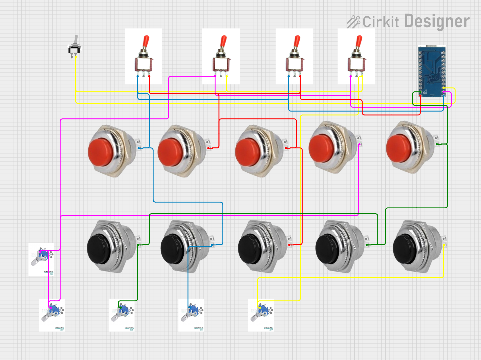
Q: Can I use a toggle switch with an Arduino? A: Yes, toggle switches can be used with an Arduino for input. Connect one terminal to an Arduino digital pin and the other to ground. Enable the internal pull-up resistor in your code.
Q: How do I know if my toggle switch is broken? A: Use a multimeter to check for continuity between the terminals when the switch is in the 'on' position. If there is no continuity, the switch may be defective.
Example Arduino Code for Reading a Toggle Switch State:
// Define the pin connected to the toggle switch
const int toggleSwitchPin = 2;

void setup() {
  // Set the toggle switch pin as input with the internal pull-up resistor enabled
  pinMode(toggleSwitchPin, INPUT_PULLUP);
  Serial.begin(9600);
}

void loop() {
  // Read the state of the toggle switch
  int switchState = digitalRead(toggleSwitchPin);

  // Print the state to the Serial Monitor
  Serial.println(switchState);

  // Add a small delay to prevent bouncing issues
  delay(50);
}
In this code, when the toggle switch is in the 'on' position, it will connect the digital pin to ground, reading LOW. When the switch is 'off', the internal pull-up resistor will pull the pin HIGH. The Serial Monitor will display '0' for 'on' and '1' for 'off'.