How to Use Arcade Button (white): Examples, Pinouts, and Specs
Introduction
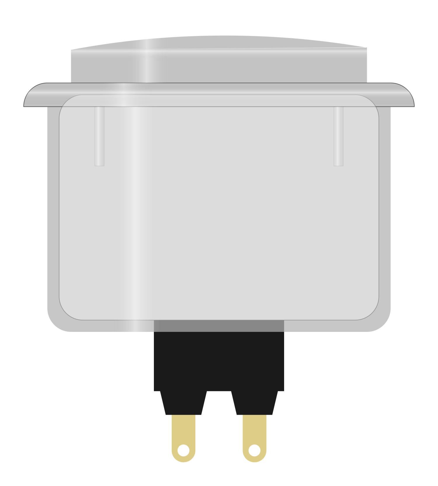
The Arcade Button (White) is a push-button switch commonly used in arcade machines. It features a durable and responsive mechanism designed for frequent user input. This button is ideal for various applications, including gaming consoles, DIY electronics projects, and interactive displays.
Explore Projects Built with Arcade Button (white)
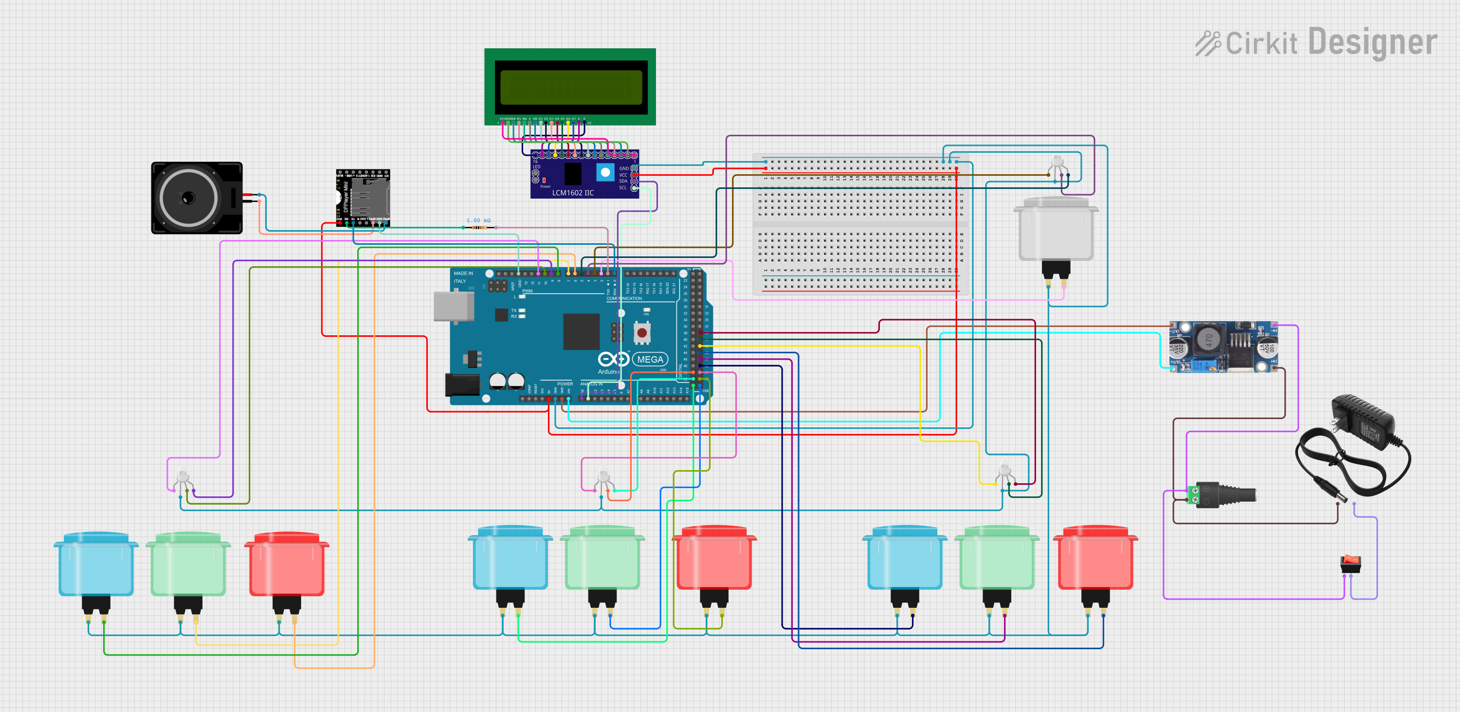
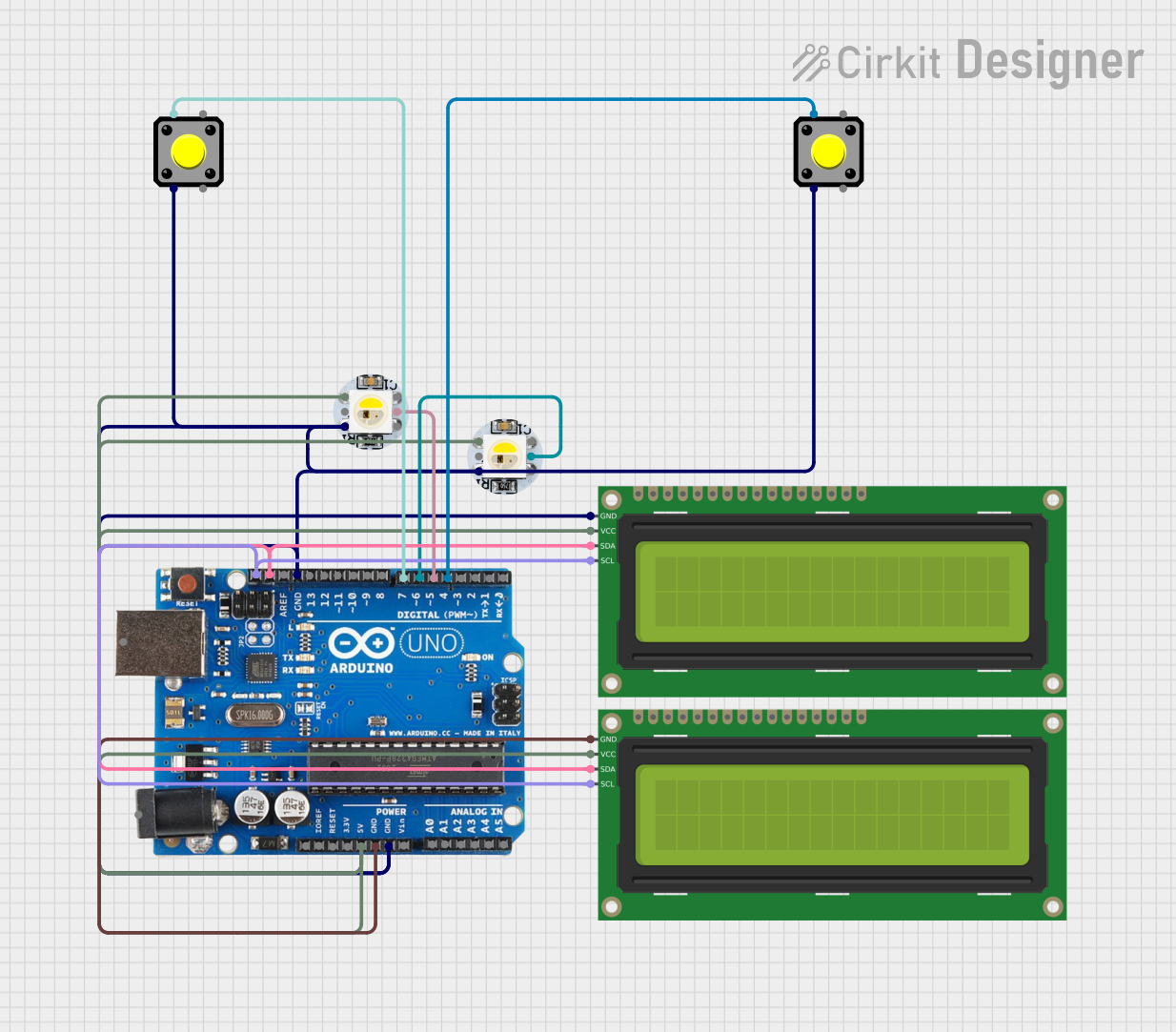
Explore Projects Built with Arcade Button (white)
Technical Specifications
Key Technical Details
| Parameter | Value |
|---|---|
| Button Type | Momentary Push-Button |
| Color | White |
| Diameter | 28 mm |
| Actuation Force | 50g |
| Contact Rating | 3A @ 125V AC |
| Mounting Hole | 24 mm |
| Terminal Type | Solder Lug |
| Material | Plastic (Housing), Metal (Contacts) |
Pin Configuration and Descriptions
The Arcade Button typically has two terminals:
| Pin Number | Description |
|---|---|
| 1 | Normally Open (NO) Contact |
| 2 | Common (COM) Contact |
Usage Instructions
How to Use the Component in a Circuit
Mounting the Button:
- Drill a 24 mm hole in your panel or enclosure.
- Insert the button into the hole and secure it using the provided nut.
Wiring the Button:
- Connect the
NOterminal to the input pin of your microcontroller or circuit. - Connect the
COMterminal to the ground (GND) of your circuit.
- Connect the
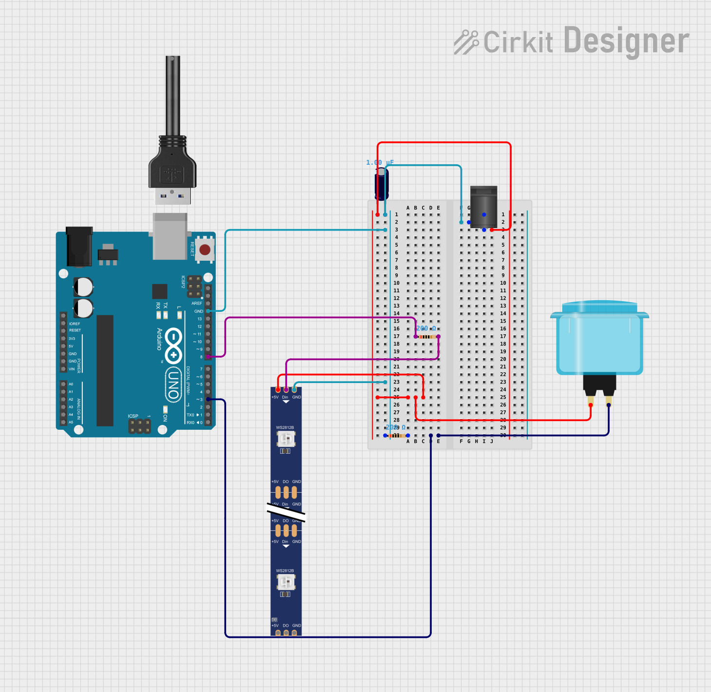
Example Circuit with Arduino UNO
Below is an example of how to connect the Arcade Button to an Arduino UNO:
Schematic
Arcade Button (White)
  +-------------------+
  |                   |
  |  NO  ----> Pin 2  |
  |  COM ----> GND    |
  |                   |
  +-------------------+
Code
// Arcade Button Example with Arduino UNO
// This code reads the state of the arcade button and turns on an LED when
// the button is pressed.

const int buttonPin = 2;  // Pin connected to NO terminal of the button
const int ledPin = 13;    // Pin connected to an LED

void setup() {
  pinMode(buttonPin, INPUT_PULLUP);  // Set button pin as input with internal pull-up
  pinMode(ledPin, OUTPUT);           // Set LED pin as output
}

void loop() {
  int buttonState = digitalRead(buttonPin);  // Read the state of the button

  if (buttonState == LOW) {  // Button is pressed
    digitalWrite(ledPin, HIGH);  // Turn on the LED
  } else {
    digitalWrite(ledPin, LOW);   // Turn off the LED
  }
}
Important Considerations and Best Practices
- Debouncing: Mechanical buttons can produce noise or "bounce" when pressed. Consider implementing software debouncing in your code to ensure reliable button presses.
- Current Rating: Ensure that the current passing through the button does not exceed its rated 3A to prevent damage.
- Mounting: Secure the button firmly to avoid any movement during operation, which could affect performance.
Troubleshooting and FAQs
Common Issues Users Might Face
Button Not Responding:
- Solution: Check the wiring connections. Ensure that the
NOterminal is connected to the correct input pin and theCOMterminal is connected to GND.
- Solution: Check the wiring connections. Ensure that the
Button Bouncing:
- Solution: Implement software debouncing in your code. You can use a simple delay or a more sophisticated debouncing algorithm.
Button Sticking:
- Solution: Ensure that the button is not physically obstructed. Clean the button mechanism if necessary.
FAQs
Q1: Can I use the Arcade Button with other microcontrollers?
- Yes, the Arcade Button can be used with any microcontroller that can read digital inputs, such as the Raspberry Pi, ESP8266, or ESP32.
Q2: How do I implement software debouncing?
- You can use a simple delay in your code to debounce the button. For example:
if (buttonState == LOW) {
  delay(50);  // Wait for 50 milliseconds
  if (digitalRead(buttonPin) == LOW) {
    // Button press is confirmed
  }
}
Q3: Can I use the Arcade Button for high-voltage applications?
- The Arcade Button is rated for 3A @ 125V AC. Ensure that your application does not exceed these ratings to prevent damage.
By following this documentation, you should be able to effectively integrate the Arcade Button (White) into your projects. Happy building!