Cirkit Designer Logo
Cirkit Designer
Your all-in-one circuit design IDE
Home / 
Component Documentation

How to Use si2302: Examples, Pinouts, and Specs

Image of si2302
Cirkit Designer LogoDesign with si2302 in Cirkit Designer

Introduction

The SI2302 is a P-channel enhancement mode field-effect transistor (MOSFET) designed for high-speed switching applications. It is commonly used in power management tasks such as load switching, as well as in circuits requiring low on-resistance and high current handling capabilities. Its small form factor and low threshold voltage make it suitable for portable electronics, power management systems, and as a switch in various electronic projects, including those involving microcontrollers like the Arduino UNO.

Explore Projects Built with si2302

Use Cirkit Designer to design, explore, and prototype these projects online. Some projects support real-time simulation. Click "Open Project" to start designing instantly!
Satellite-Based Timing and Navigation System with SDR and Atomic Clock Synchronization
Image of GPS 시스템 측정 구성도_Confirm: A project utilizing si2302 in a practical application
This circuit appears to be a complex system involving power supply management, GPS and timing synchronization, and data communication. It includes a SI-TEX G1 Satellite Compass for GPS data, an XHTF1021 Atomic Rubidium Clock for precise timing, and Ettus USRP B200 units for software-defined radio communication. Power is supplied through various SMPS units and distributed via terminal blocks and DC jacks. Data communication is facilitated by Beelink MINI S12 N95 computers, RS232 splitters, and a 1000BASE-T Media Converter for network connectivity. RF Directional Couplers are used to interface antennas with the USRP units, and the entire system is likely contained within cases for protection and organization.
Cirkit Designer LogoOpen Project in Cirkit Designer
Cellular-Enabled IoT Device with Real-Time Clock and Power Management
Image of LRCM PHASE 2 BASIC: A project utilizing si2302 in a practical application
This circuit features a LilyGo-SIM7000G module for cellular communication and GPS functionality, interfaced with an RTC DS3231 for real-time clock capabilities. It includes voltage sensing through two voltage sensor modules, and uses an 8-channel opto-coupler for isolating different parts of the circuit. Power management is handled by a buck converter connected to a DC power source and batteries, with a fuse for protection and a rocker switch for on/off control. Additionally, there's an LED for indication purposes.
Cirkit Designer LogoOpen Project in Cirkit Designer
Satellite Compass and Network-Integrated GPS Data Processing System
Image of GPS 시스템 측정 구성도_241016: A project utilizing si2302 in a practical application
This circuit comprises a satellite compass, a mini PC, two GPS antennas, power supplies, a network switch, media converters, and an atomic rubidium clock. The satellite compass is powered by a triple output DC power supply and interfaces with an RS232 splitter for 1PPS signals. The mini PCs are connected to the USRP B200 devices via USB for data and power, and to media converters via Ethernet, which in turn connect to a network switch using fiber optic links. The antennas are connected to the USRP B200s through RF directional couplers, and the atomic clock provides a 1PPS input to the RS232 splitter.
Cirkit Designer LogoOpen Project in Cirkit Designer
Arduino Mega 2560 Based Security System with Fingerprint Authentication and SMS Alerts
Image of Door security system: A project utilizing si2302 in a practical application
This circuit features an Arduino Mega 2560 microcontroller interfaced with a SIM800L GSM module, two fingerprint scanners, an I2C LCD display, an IR sensor, and a piezo buzzer. Power management is handled by a PowerBoost 1000 Basic Pad USB, a TP4056 charging module, and a Li-ion 18650 battery, with an option to use a Mini AC-DC 110V-230V to 5V 700mA module for direct power supply. The primary functionality appears to be a security system with GSM communication capabilities, biometric access control, and visual/audible feedback.
Cirkit Designer LogoOpen Project in Cirkit Designer

Explore Projects Built with si2302

Use Cirkit Designer to design, explore, and prototype these projects online. Some projects support real-time simulation. Click "Open Project" to start designing instantly!
Image of GPS 시스템 측정 구성도_Confirm: A project utilizing si2302 in a practical application
Satellite-Based Timing and Navigation System with SDR and Atomic Clock Synchronization
This circuit appears to be a complex system involving power supply management, GPS and timing synchronization, and data communication. It includes a SI-TEX G1 Satellite Compass for GPS data, an XHTF1021 Atomic Rubidium Clock for precise timing, and Ettus USRP B200 units for software-defined radio communication. Power is supplied through various SMPS units and distributed via terminal blocks and DC jacks. Data communication is facilitated by Beelink MINI S12 N95 computers, RS232 splitters, and a 1000BASE-T Media Converter for network connectivity. RF Directional Couplers are used to interface antennas with the USRP units, and the entire system is likely contained within cases for protection and organization.
Cirkit Designer LogoOpen Project in Cirkit Designer
Image of LRCM PHASE 2 BASIC: A project utilizing si2302 in a practical application
Cellular-Enabled IoT Device with Real-Time Clock and Power Management
This circuit features a LilyGo-SIM7000G module for cellular communication and GPS functionality, interfaced with an RTC DS3231 for real-time clock capabilities. It includes voltage sensing through two voltage sensor modules, and uses an 8-channel opto-coupler for isolating different parts of the circuit. Power management is handled by a buck converter connected to a DC power source and batteries, with a fuse for protection and a rocker switch for on/off control. Additionally, there's an LED for indication purposes.
Cirkit Designer LogoOpen Project in Cirkit Designer
Image of GPS 시스템 측정 구성도_241016: A project utilizing si2302 in a practical application
Satellite Compass and Network-Integrated GPS Data Processing System
This circuit comprises a satellite compass, a mini PC, two GPS antennas, power supplies, a network switch, media converters, and an atomic rubidium clock. The satellite compass is powered by a triple output DC power supply and interfaces with an RS232 splitter for 1PPS signals. The mini PCs are connected to the USRP B200 devices via USB for data and power, and to media converters via Ethernet, which in turn connect to a network switch using fiber optic links. The antennas are connected to the USRP B200s through RF directional couplers, and the atomic clock provides a 1PPS input to the RS232 splitter.
Cirkit Designer LogoOpen Project in Cirkit Designer
Image of Door security system: A project utilizing si2302 in a practical application
Arduino Mega 2560 Based Security System with Fingerprint Authentication and SMS Alerts
This circuit features an Arduino Mega 2560 microcontroller interfaced with a SIM800L GSM module, two fingerprint scanners, an I2C LCD display, an IR sensor, and a piezo buzzer. Power management is handled by a PowerBoost 1000 Basic Pad USB, a TP4056 charging module, and a Li-ion 18650 battery, with an option to use a Mini AC-DC 110V-230V to 5V 700mA module for direct power supply. The primary functionality appears to be a security system with GSM communication capabilities, biometric access control, and visual/audible feedback.
Cirkit Designer LogoOpen Project in Cirkit Designer

Technical Specifications

Key Features

  • P-Channel MOSFET
  • Drain-Source Voltage (V_DS): -20V
  • Gate-Source Voltage (V_GS): ±8V
  • Continuous Drain Current (I_D): -3.1A
  • Power Dissipation (P_D): 1.25W
  • Low on-resistance: 65mΩ at V_GS = -4.5V
  • High-speed switching capability
  • SOT-23 package for compact design
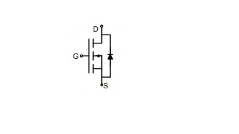
Pin Configuration

Pin Number Name Description
1 G Gate
2 S Source
3 D Drain

Usage Instructions

Integration into a Circuit

To use the SI2302 in a circuit:

  1. Connect the source (S) to the higher potential side of the load.
  2. Connect the drain (D) to the lower potential side of the load.
  3. Apply a negative voltage to the gate (G) relative to the source to turn on the MOSFET.

Best Practices

  • Ensure that the gate-source voltage (V_GS) does not exceed the ±8V limit to prevent damage.
  • Use a current limiting resistor on the gate to protect the MOSFET from high inrush currents.
  • Employ a pull-down resistor on the gate to ensure the MOSFET remains off when not actively driven.
  • Consider heat sinking if operating near the maximum power dissipation limit.

Example Circuit with Arduino UNO

The following example demonstrates how to use the SI2302 to switch a high-power LED with an Arduino UNO.

// Define the Arduino pin connected to the gate of the SI2302
const int mosfetGatePin = 3;

void setup() {
  // Set the MOSFET gate as an output
  pinMode(mosfetGatePin, OUTPUT);
}

void loop() {
  // Turn on the MOSFET by applying a LOW signal (negative voltage)
  digitalWrite(mosfetGatePin, LOW);
  delay(1000); // Keep the LED on for 1 second

  // Turn off the MOSFET by applying a HIGH signal (removing negative voltage)
  digitalWrite(mosfetGatePin, HIGH);
  delay(1000); // Keep the LED off for 1 second
}

Note: In this example, the LED's anode is connected to the power supply, and the cathode is connected to the drain of the SI2302. The source of the SI2302 is connected to the ground.

Troubleshooting and FAQs

Common Issues

  • MOSFET does not switch on: Ensure that the gate voltage is sufficiently negative relative to the source.
  • MOSFET overheating: Check if the current through the device exceeds the rated specifications or if adequate heat sinking is required.
  • Unexpected switching: Verify that there is no floating gate condition; a pull-down resistor may be necessary.

FAQs

Q: Can I use the SI2302 to switch AC loads? A: No, the SI2302 is designed for DC applications only.

Q: What is the maximum current the SI2302 can handle? A: The SI2302 can continuously conduct up to -3.1A.

Q: How can I improve the switching speed of the SI2302? A: Use a gate resistor with an appropriate value to balance switching speed and gate charge requirements.

Q: Is the SI2302 suitable for high-frequency applications? A: Yes, the SI2302 is designed for high-speed switching, making it suitable for high-frequency applications.

For further assistance or more detailed inquiries, please refer to the manufacturer's datasheet or contact technical support.