How to Use 1-Channel Relay (5V 10A): Examples, Pinouts, and Specs
Introduction
A 1-Channel Relay is an electromechanical device that acts as an electrically operated switch. It allows a low power signal to control a higher power circuit, which is essential for interfacing microcontrollers with high-power devices. This 1-Channel Relay can handle up to 10A at 5V, making it suitable for a wide range of applications, including home automation, industrial controls, and hobbyist projects.
Explore Projects Built with 1-Channel Relay (5V 10A)

Explore Projects Built with 1-Channel Relay (5V 10A)
Common Applications and Use Cases
- Turning on/off lights, fans, and other home appliances.
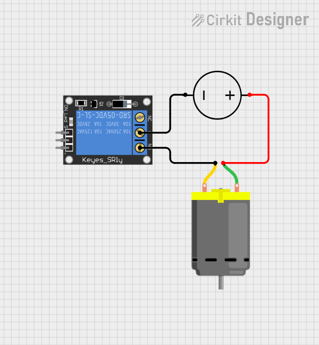
- Controlling motors, solenoids, and other actuators.
- Interfacing microcontrollers with high-power circuits.
- Isolation between a low-voltage circuit and high-voltage circuit.
Technical Specifications
Key Technical Details
- Operating Voltage (Coil): 5VDC
- Switching Voltage (Contact): Up to 250VAC or 30VDC
- Current Rating (Contact): 10A
- Switching Capacity: Up to 2500VA (AC load), 300W (DC load)
- Operate Time: 10ms (max)
- Release Time: 5ms (max)
- Electrical Life: 100,000 operations (min)
- Mechanical Life: 10,000,000 operations (min)
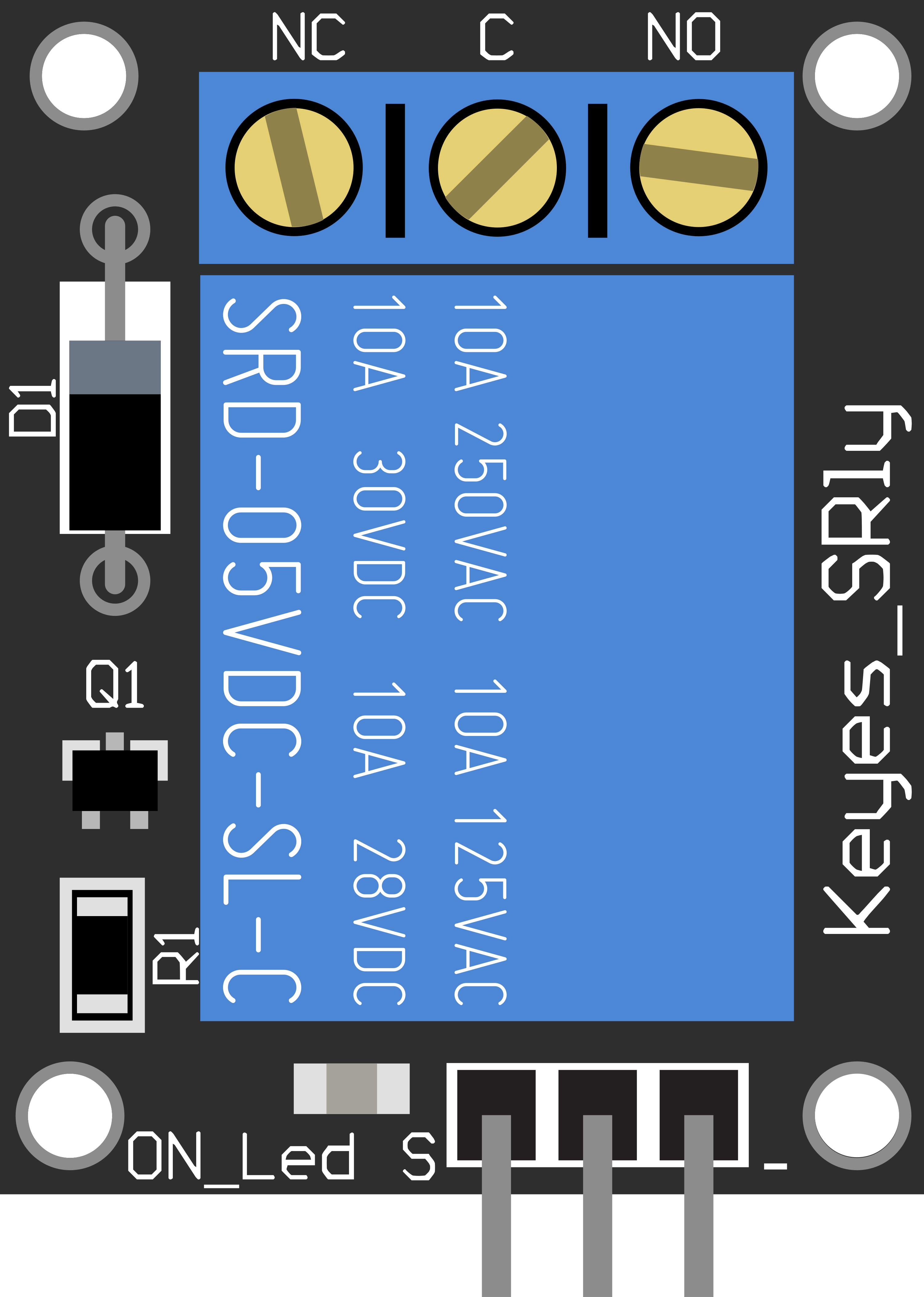
Pin Configuration and Descriptions
| Pin Number | Description | Notes |
|---|---|---|
| 1 | Normally Open (NO) | Contact opens when relay is off |
| 2 | Common (COM) | Connects to NO or NC |
| 3 | Normally Closed (NC) | Contact closes when relay is off |
| 4 | Coil Positive (VCC) | Connect to 5V supply |
| 5 | Coil Negative (GND) | Connect to ground |
| 6 | Signal (IN) | Control signal from microcontroller |
Usage Instructions
How to Use the Component in a Circuit
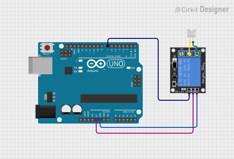
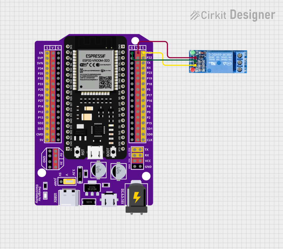
- Connect the VCC pin to a 5V power supply.
- Connect the GND pin to the ground of the power supply.
- Connect the IN pin to a digital output pin of a microcontroller.
- Connect the device you want to control to the NO or NC and COM pins, depending on whether you want the device to be on when the relay is activated (NO) or off (NC).
Important Considerations and Best Practices
- Ensure the power supply can deliver sufficient current for the relay coil.
- Use a flyback diode across the relay coil to prevent back EMF damage to the control circuit.
- Avoid using the relay at its maximum ratings for extended periods to ensure longevity.
- Consider using a snubber circuit for inductive loads to prevent arcing and noise.
- Always follow safety precautions when working with high voltage or current.
Example Code for Arduino UNO
// Define the relay control pin
const int relayPin = 2;

void setup() {
  // Set the relay pin as an output
  pinMode(relayPin, OUTPUT);
}

void loop() {
  // Turn on the relay (activate the NO contact)
  digitalWrite(relayPin, HIGH);
  delay(1000); // Wait for 1 second

  // Turn off the relay (deactivate the NO contact)
  digitalWrite(relayPin, LOW);
  delay(1000); // Wait for 1 second
}
Troubleshooting and FAQs
Common Issues
- Relay does not switch: Check the control signal and power supply connections.
- Intermittent operation: Verify that the coil voltage is stable and within specifications.
- Clicking sound but no action: Inspect the load connections and ensure they are secure.
Solutions and Tips for Troubleshooting
- Ensure all connections are secure and free from corrosion.
- Use a multimeter to check the continuity of the relay contacts.
- Test the relay coil with a separate 5V supply to confirm operation.
- If driving multiple relays, consider using a relay driver IC or transistor to handle the current.
FAQs
Q: Can I control this relay with a 3.3V microcontroller? A: While the relay coil requires 5V, some 3.3V microcontrollers can activate the relay if the input circuitry is compatible. Check the relay module's specifications.
Q: Is it safe to switch AC loads with this relay? A: Yes, but always ensure you are qualified to work with AC voltage and take appropriate safety precautions.
Q: How can I reduce electrical noise when switching the relay? A: Use a snubber circuit across the relay contacts or a flyback diode across the coil to minimize noise.
Remember, safety first when working with electricity, especially with high voltages or currents. Always consult a professional if you are unsure about working with electrical components.