
How to Use USB to 8CH TTL: Examples, Pinouts, and Specs
 Design with USB to 8CH TTL in Cirkit Designer
Introduction
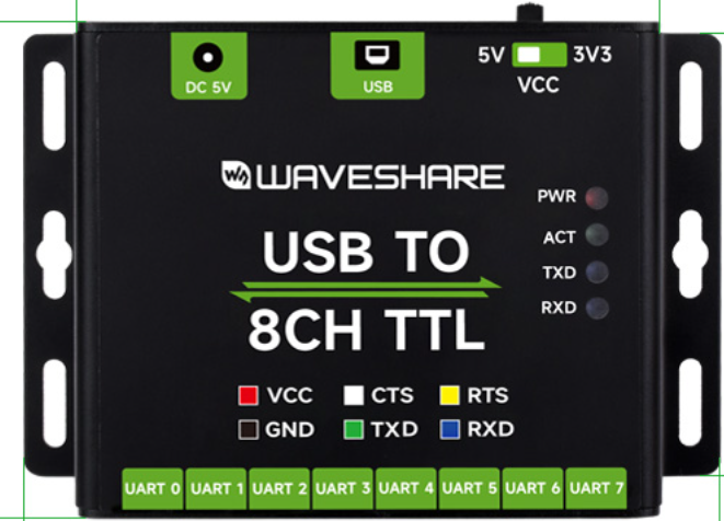
The USB to 8CH TTL module, manufactured by WaveShare (Part ID: USB-TO-8CH-TTL), is a versatile USB interface module designed to convert USB signals into 8-channel TTL (Transistor-Transistor Logic) signals. This module enables seamless communication between a computer and TTL-compatible devices, such as microcontrollers, sensors, and other digital systems. It is particularly useful in prototyping, debugging, and interfacing applications.
Explore Projects Built with USB to 8CH TTL
 Open Project in Cirkit Designer
 Open Project in Cirkit Designer
 Open Project in Cirkit Designer
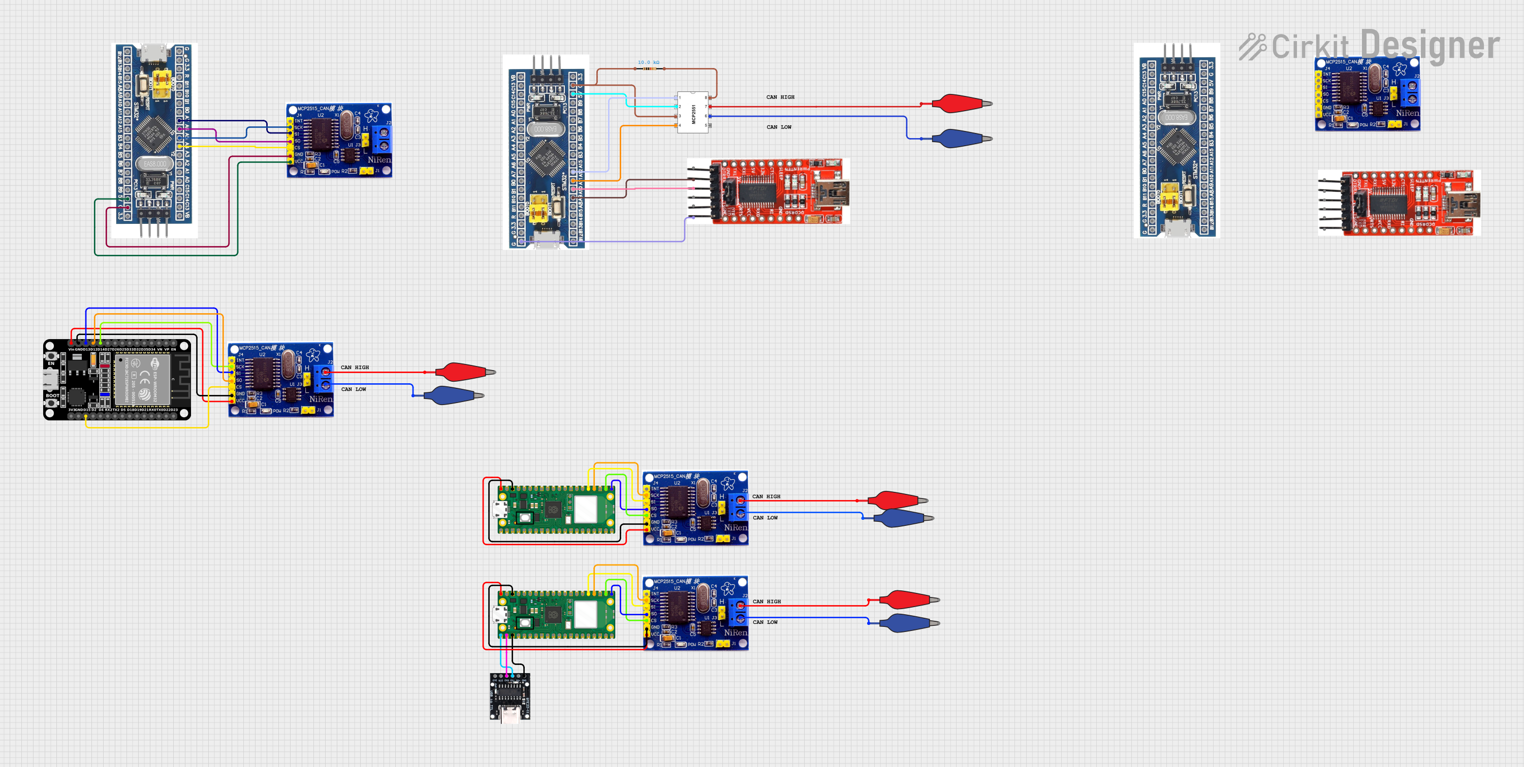 Open Project in Cirkit Designer
Explore Projects Built with USB to 8CH TTL
Open Project in Cirkit DesignerOpen Project in Cirkit DesignerOpen Project in Cirkit DesignerOpen Project in Cirkit DesignerCommon Applications and Use Cases
- Communication with microcontrollers (e.g., Arduino, STM32, Raspberry Pi)
- Interfacing with TTL-compatible sensors and modules
- Debugging and testing digital circuits
- Serial communication in embedded systems
- Data acquisition and control systems
Technical Specifications
The following table outlines the key technical details of the USB to 8CH TTL module:
| Parameter | Specification |
|---|---|
| Manufacturer | WaveShare |
| Part ID | USB-TO-8CH-TTL |
| USB Interface | USB 2.0, Type-A |
| TTL Channels | 8 independent channels |
| TTL Voltage Levels | 3.3V and 5V (selectable via jumper) |
| Baud Rate | Up to 921600 bps |
| Power Supply | Powered via USB |
| Operating Temperature | -40°C to 85°C |
| Dimensions | 60mm x 40mm |
Pin Configuration and Descriptions
The module features a 10-pin header for TTL signal connections. The pin configuration is as follows:
| Pin Number | Pin Name | Description |
|---|---|---|
| 1 | GND | Ground |
| 2 | VCC | Power supply output (3.3V or 5V, selectable) |
| 3 | TXD0 | Transmit Data Channel 0 |
| 4 | RXD0 | Receive Data Channel 0 |
| 5 | TXD1 | Transmit Data Channel 1 |
| 6 | RXD1 | Receive Data Channel 1 |
| 7 | TXD2 | Transmit Data Channel 2 |
| 8 | RXD2 | Receive Data Channel 2 |
| 9 | TXD3 | Transmit Data Channel 3 |
| 10 | RXD3 | Receive Data Channel 3 |
Note: Channels TXD4 to TXD7 and RXD4 to RXD7 are accessible via additional headers or breakout connections, depending on the module version.
Usage Instructions
How to Use the Component in a Circuit
Connect the Module to a Computer:
- Plug the USB connector of the module into a USB port on your computer.
- Ensure the necessary drivers are installed (available on the WaveShare website).
Select the TTL Voltage Level:
- Use the onboard jumper to select the desired TTL voltage level (3.3V or 5V).
Connect TTL Devices:
- Use the 10-pin header to connect the module to your TTL-compatible devices.
- Match the TXD pins of the module to the RXD pins of the device, and vice versa.
Establish Communication:
- Open a serial communication tool (e.g., PuTTY, Arduino IDE Serial Monitor) on your computer.
- Configure the baud rate and other serial settings to match your device.
Important Considerations and Best Practices
- Ensure the TTL voltage level matches the requirements of your connected device to avoid damage.
- Use proper grounding between the module and the connected device.
- Avoid exceeding the maximum baud rate of 921600 bps for reliable communication.
- If using multiple channels, ensure proper channel mapping to avoid data conflicts.
Example: Connecting to an Arduino UNO
The following example demonstrates how to use the USB to 8CH TTL module to communicate with an Arduino UNO:
Circuit Connection
- Connect the module's TXD0 pin to the Arduino's RX (Pin 0).
- Connect the module's RXD0 pin to the Arduino's TX (Pin 1).
- Connect the module's GND pin to the Arduino's GND.
Arduino Code
// Example code for Arduino UNO to communicate with USB to 8CH TTL module
void setup() {
  Serial.begin(9600); // Initialize serial communication at 9600 baud
  Serial.println("USB to 8CH TTL Module Test"); // Send test message
}

void loop() {
  if (Serial.available() > 0) {
    // Read data from the USB to 8CH TTL module
    char receivedData = Serial.read();
    // Echo the received data back to the module
    Serial.print("Received: ");
    Serial.println(receivedData);
  }
}
Note: Ensure the Arduino is not connected to its USB port while using the USB to 8CH TTL module to avoid conflicts.
Troubleshooting and FAQs
Common Issues and Solutions
Module Not Recognized by Computer:
- Ensure the USB cable is properly connected.
- Install the correct drivers from the WaveShare website.
- Try a different USB port or cable.
No Communication with TTL Device:
- Verify the TXD and RXD connections are correct.
- Check the TTL voltage level jumper setting.
- Ensure the baud rate matches the device's configuration.
Data Corruption or Loss:
- Reduce the baud rate if communication is unreliable.
- Use shorter cables to minimize signal degradation.
FAQs
Q: Can I use this module with a Raspberry Pi?
A: Yes, the module is compatible with Raspberry Pi. Connect the TXD and RXD pins to the appropriate GPIO pins on the Raspberry Pi, and ensure the voltage levels match.
Q: What is the maximum cable length for reliable communication?
A: For TTL signals, it is recommended to use cables shorter than 1 meter to maintain signal integrity.
Q: Can I power external devices using the VCC pin?
A: Yes, the VCC pin can supply 3.3V or 5V (selectable via jumper), but ensure the total current draw does not exceed the USB port's capacity (typically 500mA for USB 2.0).
This concludes the documentation for the USB to 8CH TTL module. For further assistance, refer to the WaveShare user manual or contact their support team.