How to Use dq860ma: Examples, Pinouts, and Specs
Introduction
The DQ860MA is a high-performance digital stepper motor driver designed to control stepper motors with precision and efficiency. It supports microstepping, which enables smooth motion and minimizes vibration, making it ideal for applications requiring accurate positioning and motion control. The DQ860MA is widely used in robotics, CNC machines, 3D printers, and other automated systems.
Explore Projects Built with dq860ma

Explore Projects Built with dq860ma
Common Applications:
- Robotics and automation systems
- CNC machines for milling, cutting, and engraving
- 3D printers for precise layer deposition
- Conveyor systems and industrial machinery
- Medical devices requiring accurate motion control
Technical Specifications
The DQ860MA is designed to drive stepper motors with high torque and precision. Below are its key technical details:
Key Specifications:
- Input Voltage: 24V to 80V DC
- Output Current: 2.8A to 7.8A (adjustable)
- Microstepping Resolution: Up to 256 microsteps per step
- Control Signal: Pulse/Direction or CW/CCW
- Pulse Frequency: Up to 200 kHz
- Motor Type: 2-phase or 4-phase stepper motors
- Operating Temperature: 0°C to 50°C
- Protection Features: Over-voltage, under-voltage, over-current, and short-circuit protection
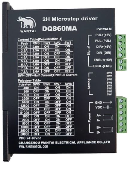
Pin Configuration and Descriptions:
The DQ860MA has a set of input and output terminals for power, control signals, and motor connections. Below is the pin configuration:
Power and Motor Connections:
| Pin Name | Description |
|---|---|
| V+ | Positive power supply input (24V-80V DC) |
| V- | Negative power supply input (GND) |
| A+ / A- | Motor winding A connections |
| B+ / B- | Motor winding B connections |
Control Signal Connections:
| Pin Name | Description |
|---|---|
| PUL+ | Pulse signal input (positive) |
| PUL- | Pulse signal input (negative) |
| DIR+ | Direction signal input (positive) |
| DIR- | Direction signal input (negative) |
| ENA+ | Enable signal input (positive) (optional) |
| ENA- | Enable signal input (negative) (optional) |
Usage Instructions
How to Use the DQ860MA in a Circuit:
- Power Supply: Connect a DC power supply (24V-80V) to the V+ and V- terminals. Ensure the power supply can provide sufficient current for the motor.
- Motor Connection: Connect the stepper motor windings to the A+/A- and B+/B- terminals. Double-check the wiring to avoid damage.
- Control Signals:
- Connect the pulse (PUL+/PUL-) and direction (DIR+/DIR-) signals to a microcontroller or motion controller.
- Optionally, connect the enable signal (ENA+/ENA-) to control the driver's activation state.
- Microstepping and Current Settings: Use the DIP switches on the driver to configure the microstepping resolution and output current. Refer to the manufacturer's datasheet for specific DIP switch settings.
- Testing: Power on the system and send pulse and direction signals to the driver. Observe the motor's motion to ensure proper operation.
Important Considerations:
- Current Setting: Set the output current to match the motor's rated current to avoid overheating or underpowering the motor.
- Signal Quality: Use shielded cables for control signals to minimize noise interference.
- Cooling: Ensure adequate ventilation or heat dissipation for the driver, especially in high-current applications.
- Polarity: Double-check the polarity of all connections to prevent damage to the driver or motor.
Example: Connecting the DQ860MA to an Arduino UNO
Below is an example of how to control the DQ860MA using an Arduino UNO:
Arduino Code:
// Define pin connections for the DQ860MA
#define PUL_PIN 2  // Pulse signal connected to Arduino pin 2
#define DIR_PIN 3  // Direction signal connected to Arduino pin 3
#define ENA_PIN 4  // Enable signal connected to Arduino pin 4

void setup() {
  // Set pin modes
  pinMode(PUL_PIN, OUTPUT);
  pinMode(DIR_PIN, OUTPUT);
  pinMode(ENA_PIN, OUTPUT);

  // Enable the driver
  digitalWrite(ENA_PIN, LOW); // LOW to enable the driver
}

void loop() {
  // Set direction
  digitalWrite(DIR_PIN, HIGH); // HIGH for one direction, LOW for the other

  // Generate pulses to move the motor
  for (int i = 0; i < 200; i++) { // 200 pulses for one revolution (example)
    digitalWrite(PUL_PIN, HIGH);
    delayMicroseconds(500); // Adjust pulse width for speed control
    digitalWrite(PUL_PIN, LOW);
    delayMicroseconds(500);
  }

  delay(1000); // Wait for 1 second before changing direction

  // Change direction
  digitalWrite(DIR_PIN, LOW);
  delay(1000); // Wait for 1 second before moving again
}
Notes:
- Adjust the
delayMicroseconds()value to control the motor speed. - Ensure the Arduino's ground is connected to the DQ860MA's signal ground (PUL-, DIR-, ENA-).
Troubleshooting and FAQs
Common Issues and Solutions:
Motor Not Moving:
- Check the power supply voltage and connections.
- Verify the pulse and direction signals are being sent correctly.
- Ensure the enable signal (ENA) is active (LOW).
Motor Vibrates but Does Not Rotate:
- Check the wiring of the motor windings (A+/A-, B+/B-).
- Verify the microstepping settings match the motor's specifications.
Overheating:
- Ensure the output current is set correctly for the motor.
- Provide adequate cooling for the driver.
Noise or Erratic Motion:
- Use shielded cables for control signals to reduce noise.
- Check for loose or faulty connections.
FAQs:
Can the DQ860MA drive a 3-phase stepper motor? No, the DQ860MA is designed for 2-phase or 4-phase stepper motors only.
What is the maximum pulse frequency supported? The DQ860MA supports pulse frequencies up to 200 kHz.
Is the enable signal mandatory? No, the enable signal is optional. If not used, the driver remains enabled by default.
Can I use the DQ860MA with a 12V power supply? No, the minimum input voltage is 24V DC. Using a lower voltage may damage the driver or result in improper operation.