How to Use R4 Minima: Examples, Pinouts, and Specs
Introduction
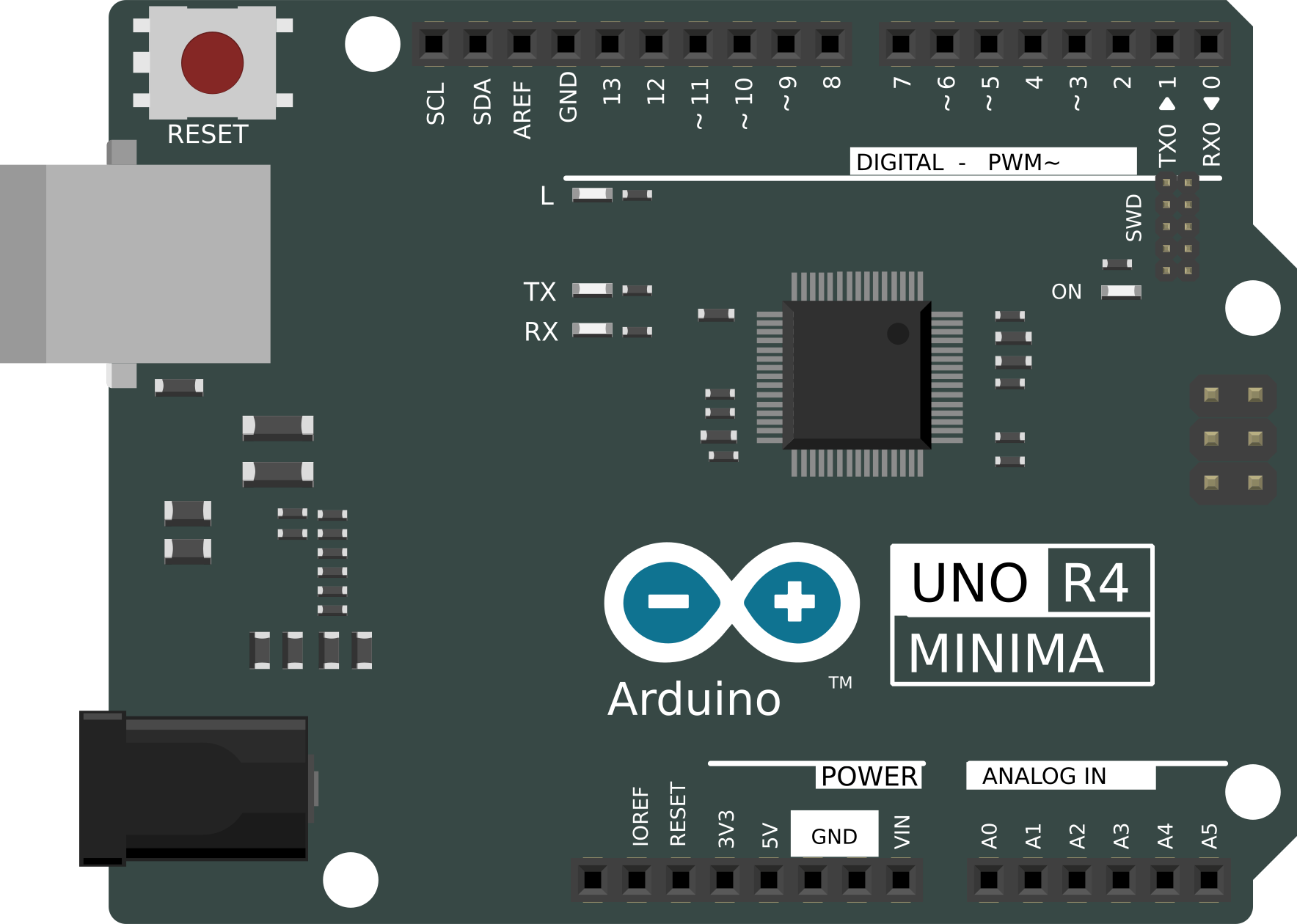
The R4 Minima is a compact resistor designed for applications where space is a critical factor. It offers precise resistance values and low power dissipation, making it ideal for modern electronic devices that require high performance in a small form factor. Its reliability and accuracy make it a popular choice for use in consumer electronics, IoT devices, and compact circuit designs.
Explore Projects Built with R4 Minima
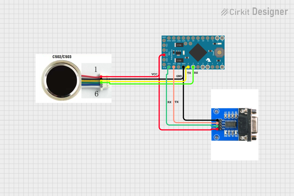
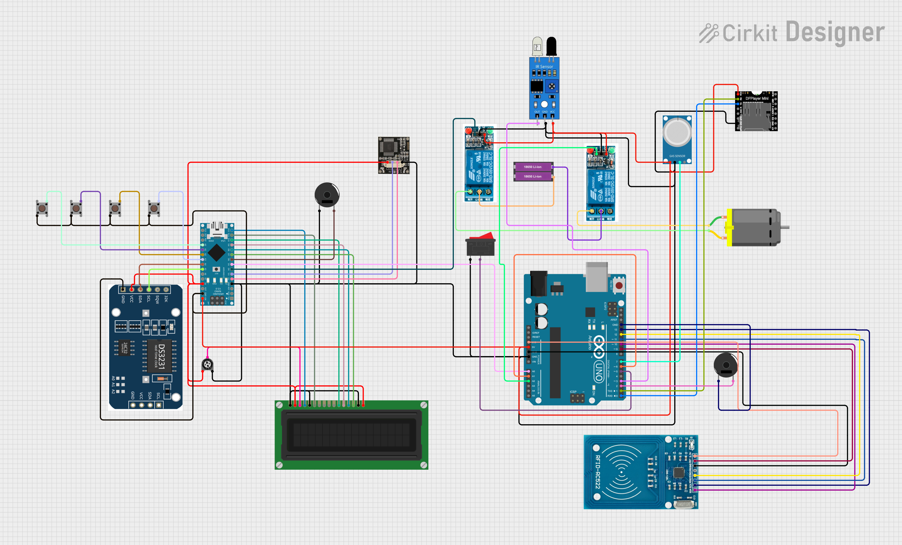
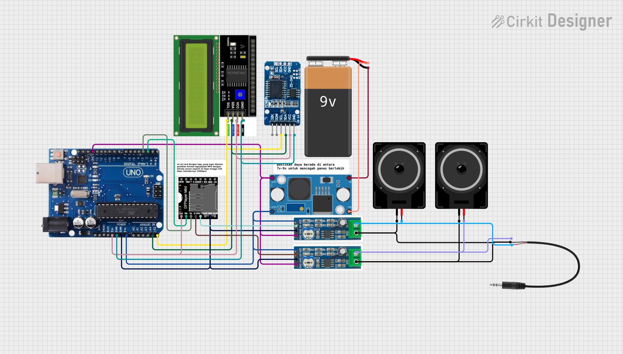
Explore Projects Built with R4 Minima
Common Applications and Use Cases
- Portable electronic devices (e.g., smartphones, wearables)
- IoT modules and sensors
- High-density PCBs
- Precision circuits requiring stable resistance values
- Low-power applications
Technical Specifications
The R4 Minima is available in various resistance values and tolerances to suit a wide range of applications. Below are the key technical details:
| Parameter | Specification |
|---|---|
| Resistance Range | 1 Ω to 1 MΩ |
| Tolerance | ±1%, ±5% |
| Power Rating | 0.125 W (1/8 W) |
| Maximum Voltage | 200 V |
| Temperature Coefficient | ±100 ppm/°C |
| Operating Temperature | -55°C to +155°C |
| Package Type | SMD (Surface-Mount Device) |
Pin Configuration and Descriptions
The R4 Minima is a two-terminal component with no polarity, making it easy to integrate into circuits. Below is the pin description:
| Pin | Description |
|---|---|
| Pin 1 | Connect to one side of the circuit |
| Pin 2 | Connect to the other side of the circuit |
Usage Instructions
How to Use the R4 Minima in a Circuit
- Determine the Required Resistance Value: Select the appropriate R4 Minima resistor based on the resistance value needed for your circuit. Refer to the resistance range and tolerance in the technical specifications.
- Placement on PCB: As an SMD component, the R4 Minima should be soldered onto the PCB pads designed for its package size. Ensure proper alignment to avoid soldering errors.
- Power Dissipation: Verify that the power dissipation in the circuit does not exceed the resistor's power rating of 0.125 W. Use the formula: [ P = I^2 \times R ] where ( P ) is power, ( I ) is current, and ( R ) is resistance.
- Voltage Rating: Ensure the voltage across the resistor does not exceed 200 V to prevent damage.
Important Considerations and Best Practices
- Thermal Management: Avoid placing the resistor near heat-sensitive components, as it may slightly heat up during operation.
- Soldering Temperature: Use a soldering temperature below 260°C to prevent damage to the resistor.
- Testing: After soldering, test the resistance value using a multimeter to ensure proper functionality.
Example: Using R4 Minima with an Arduino UNO
The R4 Minima can be used in conjunction with an Arduino UNO for various applications, such as creating a voltage divider. Below is an example of a simple voltage divider circuit:
Circuit Description
- Two R4 Minima resistors (10 kΩ each) are used to divide a 5V input voltage into 2.5V.
- The divided voltage is read by the Arduino's analog input pin.
Code Example
// Define the analog pin where the voltage divider output is connected
const int voltagePin = A0;

void setup() {
  Serial.begin(9600); // Initialize serial communication at 9600 baud
}

void loop() {
  int sensorValue = analogRead(voltagePin); // Read the analog value
  float voltage = sensorValue * (5.0 / 1023.0); // Convert to voltage
  Serial.print("Voltage: ");
  Serial.print(voltage);
  Serial.println(" V"); // Print the voltage value
  delay(1000); // Wait for 1 second before the next reading
}
Note: Ensure the total power dissipation of the resistors in the voltage divider does not exceed their combined power rating.
Troubleshooting and FAQs
Common Issues and Solutions
Incorrect Resistance Value Measured
- Cause: Poor soldering or damaged resistor.
- Solution: Recheck solder joints and replace the resistor if necessary.
Resistor Overheating
- Cause: Exceeding the power rating.
- Solution: Verify the power dissipation using the formula ( P = I^2 \times R ) and replace with a higher-rated resistor if needed.
Circuit Malfunction
- Cause: Incorrect resistor placement or value.
- Solution: Double-check the circuit design and ensure the correct resistor value is used.
FAQs
Q: Can the R4 Minima be used in high-frequency circuits?
A: Yes, the R4 Minima is suitable for high-frequency circuits due to its low inductance and compact size.
Q: Is the R4 Minima available in different package sizes?
A: Yes, the R4 Minima is available in standard SMD sizes such as 0603, 0805, and 1206.
Q: How do I calculate the required resistor value for my circuit?
A: Use Ohm's Law (( V = I \times R )) to calculate the resistance value based on the desired voltage and current.
Q: Can I use the R4 Minima in a breadboard?
A: The R4 Minima is an SMD component and is not directly compatible with breadboards. However, you can use an SMD-to-DIP adapter for breadboard prototyping.