How to Use Photocell (LDR): Examples, Pinouts, and Specs

Introduction
A photocell, or light-dependent resistor (LDR), is a sensor that varies its resistance in response to light intensity. As the light falling on the LDR increases, its resistance decreases, and vice versa. This characteristic makes photocells ideal for creating light-sensitive circuits, which are widely used in applications such as automatic night lights, outdoor clocks, and security devices.
Explore Projects Built with Photocell (LDR)
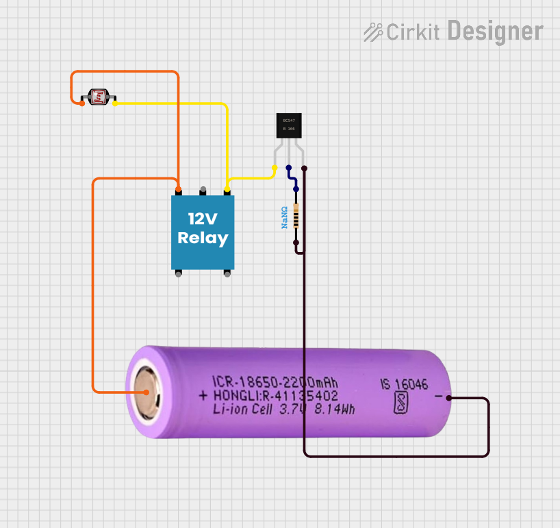
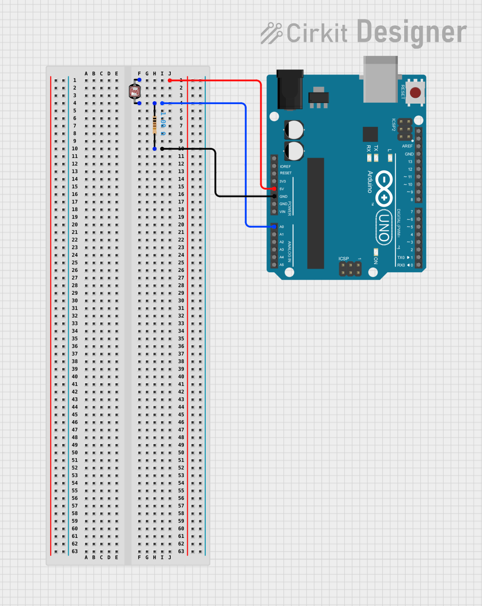
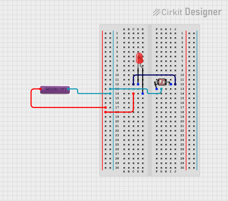
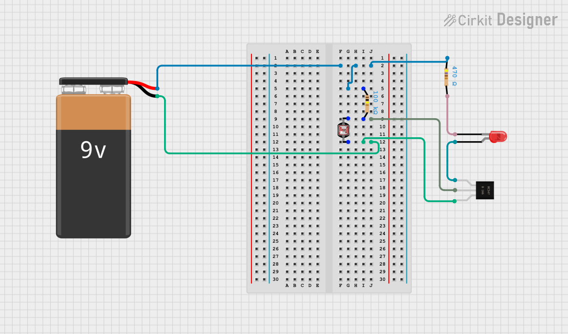
Explore Projects Built with Photocell (LDR)
Technical Specifications
Key Technical Details
- Resistance Range: Typically 1 kΩ (in bright light) to 1 MΩ (in darkness)
- Power Rating: Usually around 150 mW
- Maximum Voltage: Typically 150 V (peak)
- Light Sensitivity: Varies with the model, but generally sensitive to visible light
- Response Time: Varies from a few milliseconds to a few seconds
Pin Configuration and Descriptions
Photocells are two-terminal devices. The terminals can be connected in any orientation.
| Pin | Description |
|---|---|
| 1 | Terminal A |
| 2 | Terminal B |
Usage Instructions
Incorporating the Photocell into a Circuit
- Voltage Divider: Connect the LDR in series with a resistor to form a voltage divider. The voltage across the resistor can be used to determine the light level.
- Analog Input: When using with a microcontroller like an Arduino, connect the voltage divider output to an analog input pin.
- Polarity: The LDR does not have polarity, so it can be connected in any direction.
Best Practices
- Avoid Excessive Light: Do not expose the LDR to light levels beyond its specified range to prevent damage.
- Stable Mounting: Ensure the LDR is mounted stably to avoid fluctuations in readings due to vibrations.
- Calibration: Calibrate the LDR in the specific lighting conditions of your application for accurate readings.
Example Circuit with Arduino UNO
// Define the LDR pin
const int ldrPin = A0;

void setup() {
  // Begin serial communication at 9600 baud rate
  Serial.begin(9600);
}

void loop() {
  // Read the value from the LDR
  int ldrValue = analogRead(ldrPin);

  // Convert the analog reading (which goes from 0 - 1023) to a voltage (0 - 5V)
  float voltage = ldrValue * (5.0 / 1023.0);

  // Print out the value you read
  Serial.println(voltage);

  // Delay for a bit to avoid spamming the serial output
  delay(500);
}
Troubleshooting and FAQs
Common Issues
- Inconsistent Readings: Ensure there are no loose connections and the LDR is not subjected to intermittent light sources.
- No Change in Resistance: Verify that the LDR is not damaged and is within its operational light range.
Solutions and Tips
- Shield from Artificial Light: To measure natural light, shield the LDR from artificial light sources.
- Use a Pull-down Resistor: When the circuit seems unresponsive, ensure a proper pull-down resistor is used in the voltage divider.
FAQs
Q: Can I use the LDR to measure specific light wavelengths? A: LDRs are generally sensitive to a broad range of visible light, not specific wavelengths.
Q: How do I increase the sensitivity of the LDR circuit? A: Adjust the value of the resistor in the voltage divider to change the sensitivity.
Q: What is the lifespan of an LDR? A: LDRs can last many years, but their performance may degrade with prolonged exposure to high-intensity light.
Q: Can an LDR be used outdoors? A: Yes, but it should be protected from direct exposure to elements like water and extreme temperatures.