
How to Use NONF contactor: Examples, Pinouts, and Specs
 Design with NONF contactor in Cirkit Designer
Introduction
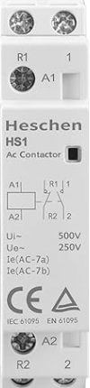
A NONF (Normally Open, Normally Closed) contactor is an electromechanical switch designed to control high-power circuits. It operates by using an electromagnetic coil to open or close its contacts, enabling or disabling the flow of electricity to a connected load. The unique feature of the NONF contactor is its dual contact configuration, which includes both normally open (NO) and normally closed (NC) contacts. This versatility makes it suitable for a wide range of applications.
Explore Projects Built with NONF contactor
 Open Project in Cirkit Designer
 Open Project in Cirkit Designer
 Open Project in Cirkit Designer
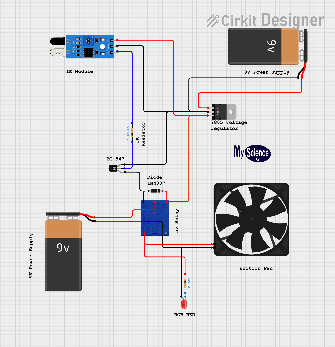 Open Project in Cirkit Designer
Explore Projects Built with NONF contactor
Open Project in Cirkit DesignerOpen Project in Cirkit DesignerOpen Project in Cirkit DesignerOpen Project in Cirkit DesignerCommon Applications and Use Cases
- Industrial motor control systems
- HVAC (Heating, Ventilation, and Air Conditioning) systems
- Lighting control in commercial buildings
- Power distribution and automation systems
- Safety interlock circuits
Technical Specifications
Key Technical Details
| Parameter | Value/Range |
|---|---|
| Coil Voltage | 12V DC, 24V DC, 110V AC, 230V AC |
| Contact Configuration | 1 NO + 1 NC, 2 NO + 2 NC |
| Rated Current | 10A, 25A, 50A, or higher (varies by model) |
| Rated Voltage | Up to 690V AC |
| Mechanical Life | 10 million operations |
| Electrical Life | 1 million operations |
| Operating Temperature | -25°C to +55°C |
| Mounting Type | DIN rail or panel-mounted |
Pin Configuration and Descriptions
The NONF contactor typically has the following pin configuration:
Power Terminals
| Pin Label | Description |
|---|---|
| L1, L2, L3 | Input power terminals for 3-phase AC (if applicable) |
| T1, T2, T3 | Output terminals to the load |
Control Terminals
| Pin Label | Description |
|---|---|
| A1 | Positive terminal for the control coil |
| A2 | Negative terminal for the control coil |
Auxiliary Contacts
| Pin Label | Description |
|---|---|
| NO | Normally Open contact (closes when coil is energized) |
| NC | Normally Closed contact (opens when coil is energized) |
Usage Instructions
How to Use the Component in a Circuit
- Determine the Coil Voltage: Verify the voltage rating of the contactor's coil (e.g., 24V DC or 230V AC) and ensure your control circuit matches this specification.
- Connect the Control Circuit:
- Connect the positive control signal to the
A1terminal. - Connect the negative or ground signal to the
A2terminal.
- Connect the positive control signal to the
- Connect the Power Circuit:
- Connect the input power lines to the
L1,L2, andL3terminals (for 3-phase systems) orL1andL2(for single-phase systems). - Connect the load to the corresponding output terminals (
T1,T2,T3).
- Connect the input power lines to the
- Utilize Auxiliary Contacts:
- Use the NO and NC terminals for auxiliary control or feedback circuits as needed.
- Test the Circuit:
- Energize the control coil by applying the appropriate voltage to
A1andA2. - Verify that the main contacts (NO and NC) operate as expected.
- Energize the control coil by applying the appropriate voltage to
Important Considerations and Best Practices
- Overcurrent Protection: Always use appropriate fuses or circuit breakers to protect the contactor and connected load.
- Avoid Coil Overvoltage: Ensure the control voltage does not exceed the rated coil voltage to prevent damage.
- Mounting: Securely mount the contactor on a DIN rail or panel to minimize vibration and ensure proper operation.
- Noise Suppression: For DC coils, consider adding a flyback diode across the coil terminals to suppress voltage spikes.
- Periodic Maintenance: Inspect the contactor periodically for wear and ensure the contacts are clean and free of debris.
Example: Connecting a NONF Contactor to an Arduino UNO
Below is an example of how to control a 12V DC NONF contactor using an Arduino UNO and a relay module.
// Define the pin connected to the relay module
const int relayPin = 7;

void setup() {
  // Set the relay pin as an output
  pinMode(relayPin, OUTPUT);

  // Ensure the relay is off at startup
  digitalWrite(relayPin, LOW);
}

void loop() {
  // Turn the relay (and contactor) ON
  digitalWrite(relayPin, HIGH);
  delay(5000); // Keep the contactor ON for 5 seconds

  // Turn the relay (and contactor) OFF
  digitalWrite(relayPin, LOW);
  delay(5000); // Keep the contactor OFF for 5 seconds
}
Note: The relay module is used to isolate the Arduino from the high-power contactor. Ensure the relay module can handle the contactor's coil current.
Troubleshooting and FAQs
Common Issues Users Might Face
Contactor Does Not Operate:
- Cause: Incorrect control voltage or loose connections.
- Solution: Verify the control voltage matches the coil rating and check all connections.
Contacts Overheat:
- Cause: Overcurrent or poor contact quality.
- Solution: Ensure the load current does not exceed the contactor's rated current. Inspect and clean the contacts if necessary.
Excessive Noise During Operation:
- Cause: Coil vibration or insufficient mounting.
- Solution: Securely mount the contactor and check for proper coil voltage.
Auxiliary Contacts Not Functioning:
- Cause: Miswiring or damaged contacts.
- Solution: Verify the wiring and inspect the auxiliary contacts for wear.
Solutions and Tips for Troubleshooting
- Use a multimeter to check the continuity of the NO and NC contacts when the coil is energized and de-energized.
- If the contactor fails to energize, measure the voltage across the coil terminals (
A1andA2) to ensure proper control voltage is applied. - For DC coils, check the flyback diode (if installed) for proper orientation and functionality.
By following this documentation, users can effectively integrate and troubleshoot a NONF contactor in their electrical systems.