Cirkit Designer Logo
Cirkit Designer
Your all-in-one circuit design IDE
Home / 
Component Documentation

How to Use Servo: Examples, Pinouts, and Specs

Image of Servo
Cirkit Designer LogoDesign with Servo in Cirkit Designer

Introduction

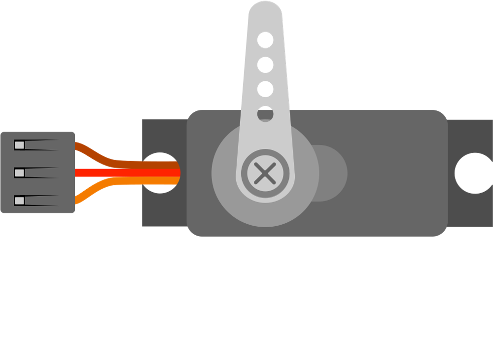
A servo is a rotary actuator that allows for precise control of angular position, velocity, and acceleration. It consists of a motor coupled to a sensor for position feedback, along with a control circuit. Servos are widely used in robotics, automation, remote-controlled vehicles, and industrial machinery due to their ability to provide accurate and repeatable motion.

Explore Projects Built with Servo

Use Cirkit Designer to design, explore, and prototype these projects online. Some projects support real-time simulation. Click "Open Project" to start designing instantly!
Arduino Mega 2560 Controlled Multi-Servo Random Positioning System
Image of robotic: A project utilizing Servo in a practical application
This circuit consists of an Arduino Mega 2560 microcontroller connected to twelve servo motors, each individually controlled by a distinct PWM pin on the Arduino. The servos are powered by a single Polymer Lithium Ion Battery, with all servos sharing a common power (VCC) and ground (GND) connection. The embedded code on the Arduino is designed to randomly position each servo within a 0 to 180-degree range, with a random delay between movements, demonstrating a multi-servo control system possibly for applications like robotics or animatronics.
Cirkit Designer LogoOpen Project in Cirkit Designer
Arduino UNO Servo Motor Controller
Image of Test project: A project utilizing Servo in a practical application
This circuit consists of an Arduino UNO microcontroller connected to a servo motor. The Arduino provides power (5V and GND) to the servo and controls its position through a pulse signal on pin D9. The embedded code on the Arduino is programmed to smoothly move the servo between 0 and 180 degrees, creating a sweeping motion.
Cirkit Designer LogoOpen Project in Cirkit Designer
Arduino UNO Controlled Servo Motor
Image of lblblblb: A project utilizing Servo in a practical application
This circuit consists of an Arduino UNO microcontroller connected to a servo motor. The Arduino provides power (5V) and ground connections to the servo, as well as a control signal through one of its digital pins (D6). The embedded code on the Arduino is set up to control the servo's position, sending it to a fixed angle upon each loop iteration.
Cirkit Designer LogoOpen Project in Cirkit Designer
Arduino-Controlled Multi-Servo System
Image of Mind controlled robotic arm: A project utilizing Servo in a practical application
This circuit consists of an Arduino UNO microcontroller connected to five servo motors. The servos are powered by the Arduino's 5V output and share a common ground. Each servo's PWM control pin is individually connected to a digital pin on the Arduino (D8, D9, D10, D11, D12), allowing for independent control of each servo's position. The Arduino is also connected to a laptop via USB for programming and power.
Cirkit Designer LogoOpen Project in Cirkit Designer

Explore Projects Built with Servo

Use Cirkit Designer to design, explore, and prototype these projects online. Some projects support real-time simulation. Click "Open Project" to start designing instantly!
Image of robotic: A project utilizing Servo in a practical application
Arduino Mega 2560 Controlled Multi-Servo Random Positioning System
This circuit consists of an Arduino Mega 2560 microcontroller connected to twelve servo motors, each individually controlled by a distinct PWM pin on the Arduino. The servos are powered by a single Polymer Lithium Ion Battery, with all servos sharing a common power (VCC) and ground (GND) connection. The embedded code on the Arduino is designed to randomly position each servo within a 0 to 180-degree range, with a random delay between movements, demonstrating a multi-servo control system possibly for applications like robotics or animatronics.
Cirkit Designer LogoOpen Project in Cirkit Designer
Image of Test project: A project utilizing Servo in a practical application
Arduino UNO Servo Motor Controller
This circuit consists of an Arduino UNO microcontroller connected to a servo motor. The Arduino provides power (5V and GND) to the servo and controls its position through a pulse signal on pin D9. The embedded code on the Arduino is programmed to smoothly move the servo between 0 and 180 degrees, creating a sweeping motion.
Cirkit Designer LogoOpen Project in Cirkit Designer
Image of lblblblb: A project utilizing Servo in a practical application
Arduino UNO Controlled Servo Motor
This circuit consists of an Arduino UNO microcontroller connected to a servo motor. The Arduino provides power (5V) and ground connections to the servo, as well as a control signal through one of its digital pins (D6). The embedded code on the Arduino is set up to control the servo's position, sending it to a fixed angle upon each loop iteration.
Cirkit Designer LogoOpen Project in Cirkit Designer
Image of Mind controlled robotic arm: A project utilizing Servo in a practical application
Arduino-Controlled Multi-Servo System
This circuit consists of an Arduino UNO microcontroller connected to five servo motors. The servos are powered by the Arduino's 5V output and share a common ground. Each servo's PWM control pin is individually connected to a digital pin on the Arduino (D8, D9, D10, D11, D12), allowing for independent control of each servo's position. The Arduino is also connected to a laptop via USB for programming and power.
Cirkit Designer LogoOpen Project in Cirkit Designer

Common Applications and Use Cases

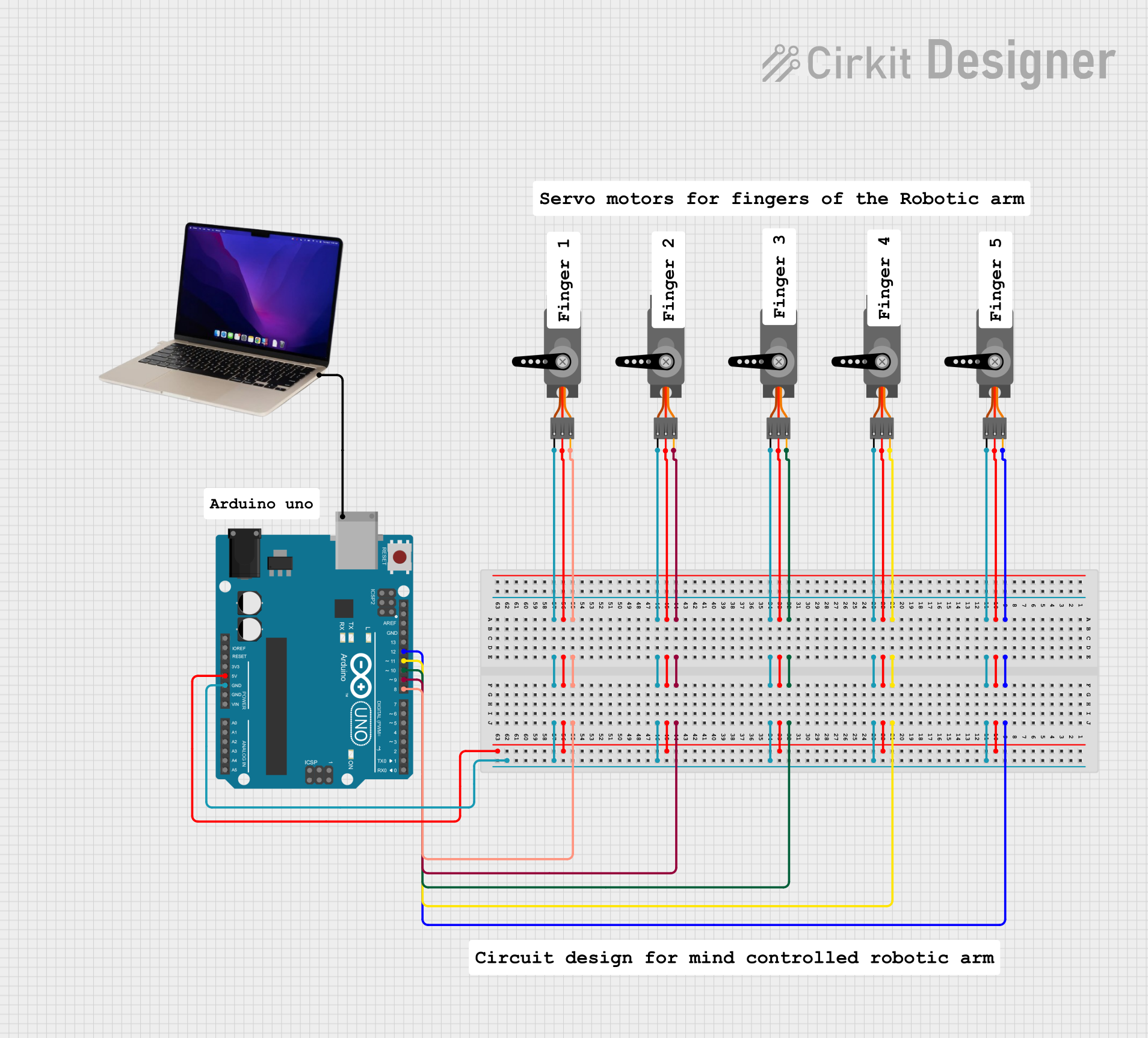
  • Robotics: Used for controlling robotic arms, grippers, and joints.
  • RC Vehicles: Steering mechanisms in cars, planes, and boats.
  • Automation: Positioning systems in conveyor belts and manufacturing equipment.
  • DIY Projects: Commonly used in hobbyist projects for creating moving parts.
  • Camera Gimbals: Stabilizing and positioning cameras for smooth motion.

Technical Specifications

Below are the general technical specifications for a standard hobby servo. Note that specifications may vary depending on the specific model and manufacturer.

Key Technical Details

  • Operating Voltage: 4.8V to 6V (typical range)
  • Operating Current: 100mA to 1A (depending on load)
  • Torque: 1.5 kg-cm to 20 kg-cm (varies by model)
  • Rotation Range: 0° to 180° (standard), 360° for continuous rotation servos
  • Control Signal: Pulse Width Modulation (PWM)
  • Pulse Width Range: 1ms (0°) to 2ms (180°)
  • Neutral Position: 1.5ms (90°)
  • Connector Type: 3-pin (Signal, VCC, GND)

Pin Configuration and Descriptions

The servo typically has a 3-pin connector with the following configuration:

Pin Number Name Description
1 Signal Receives PWM signal for position control
2 VCC Power supply (4.8V to 6V)
3 GND Ground connection

Usage Instructions

How to Use the Servo in a Circuit

  1. Power the Servo: Connect the VCC pin to a 5V or 6V power source and the GND pin to the ground of your circuit.
  2. Control Signal: Connect the Signal pin to a PWM-capable pin on your microcontroller (e.g., Arduino).
  3. PWM Signal: Generate a PWM signal with a pulse width between 1ms and 2ms to control the servo's position:
    • 1ms corresponds to 0°.
    • 1.5ms corresponds to 90° (neutral position).
    • 2ms corresponds to 180°.

Important Considerations and Best Practices

  • Power Supply: Use a separate power supply for the servo if it draws significant current, as it may cause voltage drops in your circuit.
  • Avoid Overloading: Do not exceed the torque rating of the servo to prevent damage.
  • Signal Stability: Ensure the PWM signal is stable and within the specified range to avoid erratic behavior.
  • Continuous Rotation Servos: For continuous rotation servos, the PWM signal controls speed and direction rather than position.

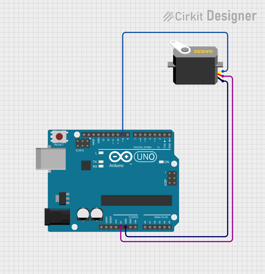
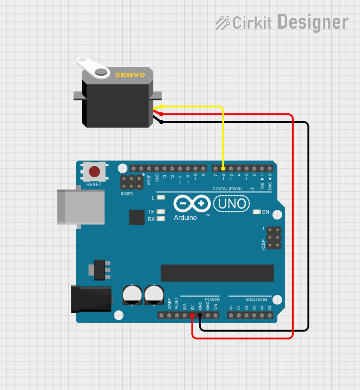
Example: Connecting a Servo to an Arduino UNO

Below is an example of how to control a servo using an Arduino UNO:

#include <Servo.h> // Include the Servo library

Servo myServo; // Create a Servo object

void setup() {
  myServo.attach(9); // Attach the servo to pin 9 on the Arduino
}

void loop() {
  myServo.write(0); // Move the servo to 0 degrees
  delay(1000);      // Wait for 1 second

  myServo.write(90); // Move the servo to 90 degrees
  delay(1000);       // Wait for 1 second

  myServo.write(180); // Move the servo to 180 degrees
  delay(1000);        // Wait for 1 second
}

Code Explanation

  • The Servo library simplifies controlling the servo.
  • The attach() function links the servo to a specific PWM pin.
  • The write() function sets the servo's position in degrees (0° to 180°).
  • Delays are used to allow the servo to reach the desired position before the next command.

Troubleshooting and FAQs

Common Issues and Solutions

  1. Servo Not Moving:

    • Cause: Insufficient power supply.
    • Solution: Use a dedicated power source with sufficient current capacity.
  2. Erratic Movement:

    • Cause: Unstable or noisy PWM signal.
    • Solution: Check the signal source and ensure proper grounding.
  3. Overheating:

    • Cause: Overloading the servo or running it continuously at high torque.
    • Solution: Reduce the load or use a higher-torque servo.
  4. Limited Range of Motion:

    • Cause: Incorrect PWM signal range.
    • Solution: Verify the pulse width range (1ms to 2ms) and adjust your code.

FAQs

  • Q: Can I power the servo directly from the Arduino?

    • A: While possible for small servos, it is not recommended for larger servos due to current limitations. Use an external power supply.
  • Q: How do I control a continuous rotation servo?

    • A: Instead of position, the PWM signal controls speed and direction. A 1.5ms pulse stops the servo, while shorter or longer pulses control direction and speed.
  • Q: Can I connect multiple servos to a single Arduino?

    • A: Yes, but ensure the power supply can handle the combined current draw of all servos.
  • Q: What happens if I send a pulse width outside the 1ms to 2ms range?

    • A: The servo may behave unpredictably or stop responding. Always stay within the specified range.

This documentation provides a comprehensive guide to understanding and using a servo in your projects. Follow the guidelines and best practices to ensure optimal performance and longevity of your servo.