
How to Use KeyPad Pin Header: Examples, Pinouts, and Specs

 Design with KeyPad Pin Header in Cirkit Designer
Introduction
A KeyPad Pin Header is a connector designed to facilitate the connection of a keypad to a microcontroller or circuit board. It provides a reliable and convenient interface, allowing for easy connection and disconnection without the need for soldering. These pin headers are commonly used in projects involving user input, such as password-protected systems, menu navigation, or other applications requiring a keypad interface.
Explore Projects Built with KeyPad Pin Header
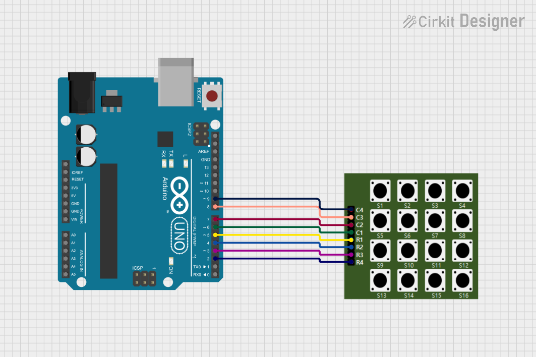 Open Project in Cirkit Designer
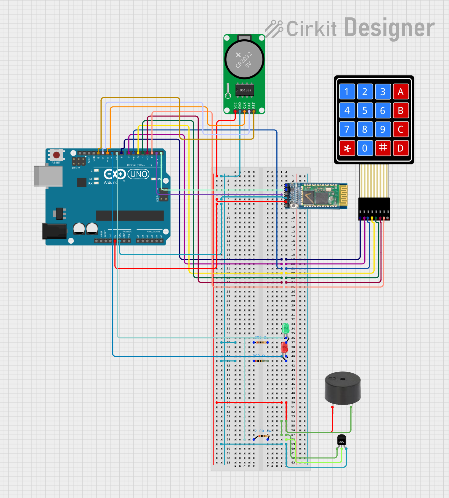 Open Project in Cirkit Designer
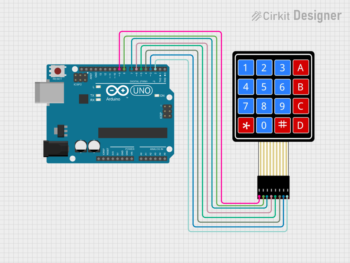 Open Project in Cirkit Designer
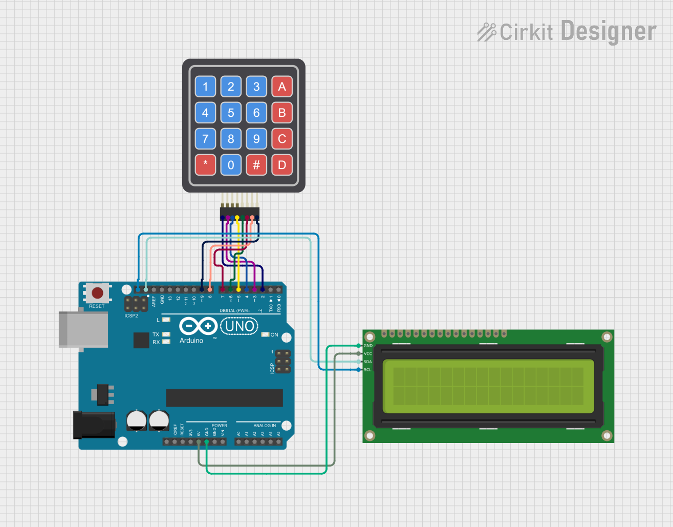 Open Project in Cirkit Designer
Explore Projects Built with KeyPad Pin Header
Open Project in Cirkit DesignerOpen Project in Cirkit DesignerOpen Project in Cirkit DesignerOpen Project in Cirkit DesignerCommon Applications and Use Cases
- Interfacing keypads with microcontrollers (e.g., Arduino, Raspberry Pi)
- Security systems (e.g., password entry)
- Home automation control panels
- Industrial equipment requiring user input
- Prototyping and testing circuits with keypads
Technical Specifications
Key Specifications
- Number of Pins: Typically 4, 8, or 12 pins, depending on the keypad type (e.g., 4x3 or 4x4 matrix keypads)
- Pin Pitch: Standard 2.54 mm (0.1 inch)
- Current Rating: Up to 3A (varies by manufacturer)
- Voltage Rating: Up to 250V (varies by manufacturer)
- Material: Gold-plated or tin-plated copper for corrosion resistance
- Mounting Type: Through-hole or surface-mount
- Durability: Rated for 1000+ mating cycles
Pin Configuration and Descriptions
The pin configuration of a KeyPad Pin Header depends on the type of keypad it is designed to interface with. Below is an example for a 4x4 matrix keypad:
| Pin Number | Description | Connection Type |
|---|---|---|
| 1 | Row 1 | Connect to microcontroller GPIO |
| 2 | Row 2 | Connect to microcontroller GPIO |
| 3 | Row 3 | Connect to microcontroller GPIO |
| 4 | Row 4 | Connect to microcontroller GPIO |
| 5 | Column 1 | Connect to microcontroller GPIO |
| 6 | Column 2 | Connect to microcontroller GPIO |
| 7 | Column 3 | Connect to microcontroller GPIO |
| 8 | Column 4 | Connect to microcontroller GPIO |
For a 4x3 keypad, pins 7 and 8 would typically be omitted.
Usage Instructions
How to Use the Component in a Circuit
- Identify the Pinout: Refer to the keypad's datasheet or documentation to determine the pinout.
- Connect to Microcontroller: Use jumper wires or a ribbon cable to connect the KeyPad Pin Header to the microcontroller's GPIO pins.
- Pull-Up or Pull-Down Resistors: Ensure that the microcontroller's GPIO pins are configured with internal pull-up or pull-down resistors, as required.
- Matrix Scanning: Implement a matrix scanning algorithm in your microcontroller code to detect key presses.
Important Considerations and Best Practices
- Debouncing: Keypads may produce noise or multiple signals when a key is pressed. Use software debouncing techniques to filter out false signals.
- Voltage Levels: Ensure that the voltage levels of the microcontroller and keypad are compatible.
- Secure Connections: Use locking connectors or headers to prevent accidental disconnection in critical applications.
- Avoid Overcurrent: Do not exceed the current rating of the pin header to prevent damage.
Example Code for Arduino UNO
Below is an example of interfacing a 4x4 keypad with an Arduino UNO using the KeyPad Pin Header:
#include <Keypad.h>

// Define the rows and columns of the keypad
const byte ROWS = 4; // Four rows
const byte COLS = 4; // Four columns

// Define the keymap for the keypad
char keys[ROWS][COLS] = {
  {'1', '2', '3', 'A'},
  {'4', '5', '6', 'B'},
  {'7', '8', '9', 'C'},
  {'*', '0', '#', 'D'}
};

// Define the pin connections for rows and columns
byte rowPins[ROWS] = {9, 8, 7, 6}; // Connect to Row 1, 2, 3, 4
byte colPins[COLS] = {5, 4, 3, 2}; // Connect to Column 1, 2, 3, 4

// Create a Keypad object
Keypad keypad = Keypad(makeKeymap(keys), rowPins, colPins, ROWS, COLS);

void setup() {
  Serial.begin(9600); // Initialize serial communication
  Serial.println("Keypad Test: Press a key");
}

void loop() {
  char key = keypad.getKey(); // Get the key pressed
  if (key) {
    Serial.print("Key Pressed: ");
    Serial.println(key); // Print the key to the serial monitor
  }
}
Troubleshooting and FAQs
Common Issues and Solutions
Keypad Not Responding:
- Cause: Incorrect pin connections.
- Solution: Double-check the pinout and ensure proper connections between the keypad and the microcontroller.
Multiple Key Presses Detected:
- Cause: Key bouncing.
- Solution: Implement software debouncing in your code.
Incorrect Key Mapping:
- Cause: Mismatch between the physical keypad layout and the keymap in the code.
- Solution: Verify the keymap in the code matches the keypad's layout.
Loose Connections:
- Cause: Poor contact between the pin header and the connector.
- Solution: Use locking connectors or ensure a snug fit.
FAQs
Q: Can I use a KeyPad Pin Header with a 3x4 keypad?
A: Yes, simply connect the appropriate pins for the 3x4 keypad and adjust the code accordingly.Q: What type of cable should I use with the pin header?
A: Ribbon cables or individual jumper wires with a 2.54 mm pitch are commonly used.Q: How do I prevent accidental disconnections?
A: Use locking connectors or secure the pin header with adhesive or a mounting bracket.
This documentation provides a comprehensive guide to understanding and using a KeyPad Pin Header effectively in your projects.