How to Use 12978-alligator_clip_cable_half-red: Examples, Pinouts, and Specs
Introduction
The 12978-alligator_clip_cable_half-red is a versatile and essential tool for hobbyists, engineers, and technicians alike. This red alligator clip cable is designed for creating temporary electrical connections, which is particularly useful during prototyping, testing, and troubleshooting of electronic circuits. Its ease of use and quick application make it a staple in any electronic toolkit.
Explore Projects Built with 12978-alligator_clip_cable_half-red
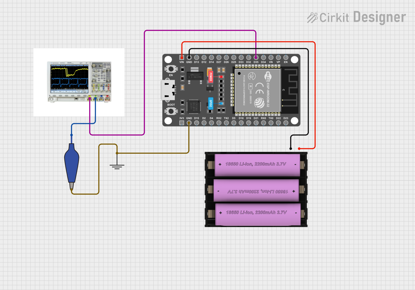


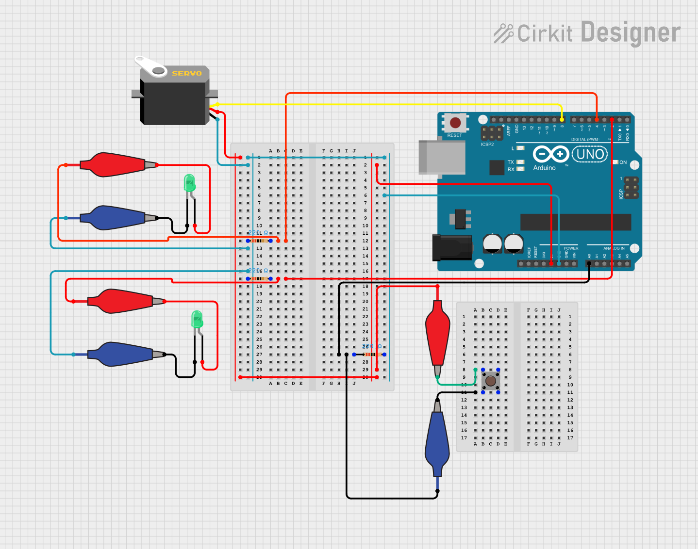
Explore Projects Built with 12978-alligator_clip_cable_half-red
Common Applications and Use Cases
- Prototyping electronic circuits
- Testing components within a circuit
- Temporary connections for electrical testing
- Educational purposes in classrooms and labs
- Repairing connections in automotive and home electronics
Technical Specifications
The 12978-alligator_clip_cable_half-red is characterized by its simplicity and ease of use. Below are the key technical details and pin configuration for this component.
Key Technical Details
| Specification | Detail |
|---|---|
| Cable Length | Typically 15-30 cm (6-12 inches) |
| Cable Gauge | Varies (commonly 22-24 AWG) |
| Maximum Voltage | Varies (commonly up to 30V) |
| Maximum Current | Varies (commonly up to 5A) |
| Insulation Material | PVC or Rubber |
| Clip Material | Metal with insulation cover |
| Clip Jaw Opening | Approximately 8 mm |
| Color | Red (indicating positive lead) |
Pin Configuration and Descriptions
The 12978-alligator_clip_cable_half-red does not have a pin configuration in the traditional sense, as it is a single cable with an alligator clip at one end. The clip serves as the point of contact for electrical connections.
Usage Instructions
How to Use the Component in a Circuit
- Identify Connection Points: Determine the points in the circuit where a temporary connection is needed.
- Open the Alligator Clip: Press the tail of the clip to open the jaws.
- Attach the Clip: Secure the alligator clip to the connection point, ensuring a firm grip to maintain a stable electrical connection.
- Connect to Equipment: The other end of the cable can be connected to test equipment, another circuit, or a breadboard as required.
Important Considerations and Best Practices
- Insulation Check: Ensure the insulation on the cable and clip is intact to prevent accidental shorts.
- Connection Quality: Verify that the alligator clip has a strong grip on the connection point to ensure a reliable connection.
- Voltage and Current Ratings: Do not exceed the voltage and current ratings of the cable to avoid damage or injury.
- Color Coding: Use the red color as an indicator for positive voltage connections in a DC circuit, and maintain consistent color coding for clarity.
- Safety Precautions: When working with higher voltages or currents, take appropriate safety measures to prevent electric shock.
Troubleshooting and FAQs
Common Issues Users Might Face
- Loose Connections: If the connection is intermittent, check that the alligator clip is firmly attached to the connection point.
- Insulation Damage: Inspect the cable and clip for any damage to the insulation which could lead to shorts.
- Corrosion: Over time, the metal parts of the clip may corrode, which can affect conductivity. Clean or replace the clip as necessary.
Solutions and Tips for Troubleshooting
- Ensure a Clean Contact: Make sure the contact points are clean and free of debris before attaching the alligator clip.
- Check for Continuity: Use a multimeter to check for continuity in the cable if you suspect a break or fault within the wire.
- Replace if Necessary: If the alligator clip is damaged or not functioning properly, replace it with a new one to ensure safety and reliability.
FAQs
Q: Can I use the 12978-alligator_clip_cable_half-red for AC circuits? A: Yes, but ensure that the voltage and current ratings are within the specifications of the cable.
Q: How do I prevent the alligator clips from slipping off the connection points? A: Make sure the clip's jaws are clean and that they have a firm grip on the connection point. If necessary, clean the jaws to improve grip.
Q: Is it safe to use alligator clips for high-power applications? A: Alligator clips are not recommended for high-power applications. Always adhere to the specified voltage and current ratings.
Q: Can I extend the length of the alligator clip cable? A: Yes, you can solder or twist another wire to the end of the cable, but ensure that the extension wire can handle the same or higher current and voltage ratings.
Q: How do I differentiate between positive and negative leads when using multiple alligator clips? A: It is common practice to use red for positive and black for negative leads. Always maintain consistent color coding to avoid confusion.
Example Code for Arduino UNO Connection
// No specific code is required for using an alligator clip cable with an Arduino UNO.
// However, here is an example of how you might use it to connect a simple pushbutton.

const int buttonPin = 2; // Pin connected to the button
int buttonState = 0;     // Variable to store button state

void setup() {
  pinMode(buttonPin, INPUT); // Initialize the button pin as an input
}

void loop() {
  buttonState = digitalRead(buttonPin); // Read the state of the button
  if (buttonState == HIGH) {
    // If the button is pressed (assuming the other side of the button is connected to GND)
    // Perform an action
  } else {
    // If the button is not pressed
    // Perform another action or do nothing
  }
}
In this example, you could use the 12978-alligator_clip_cable_half-red to connect one side of the pushbutton to pin 2 on the Arduino UNO. The other side of the pushbutton would typically be connected to ground, possibly with another alligator clip cable of a different color (commonly black).