How to Use 24_PSU: Examples, Pinouts, and Specs

 Design with 24_PSU in Cirkit Designer
Introduction
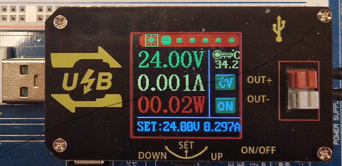
The 24V Power Supply Unit (24_PSU) is an essential device that converts alternating current (AC) from the mains electricity supply into a stable 24-volt direct current (DC) output. This PSU is widely used in industrial control systems, automation, telecommunications, and other electronic applications where a reliable 24V DC power source is required.
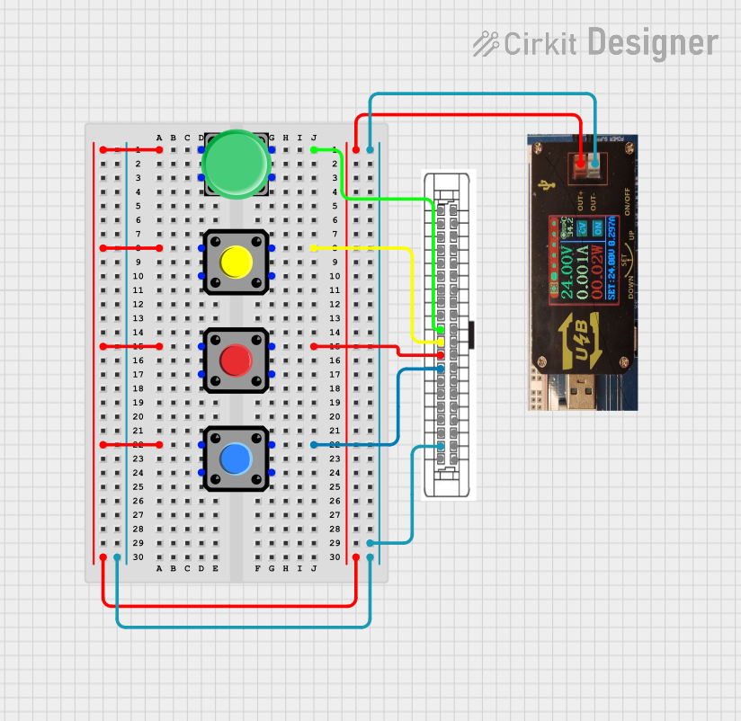
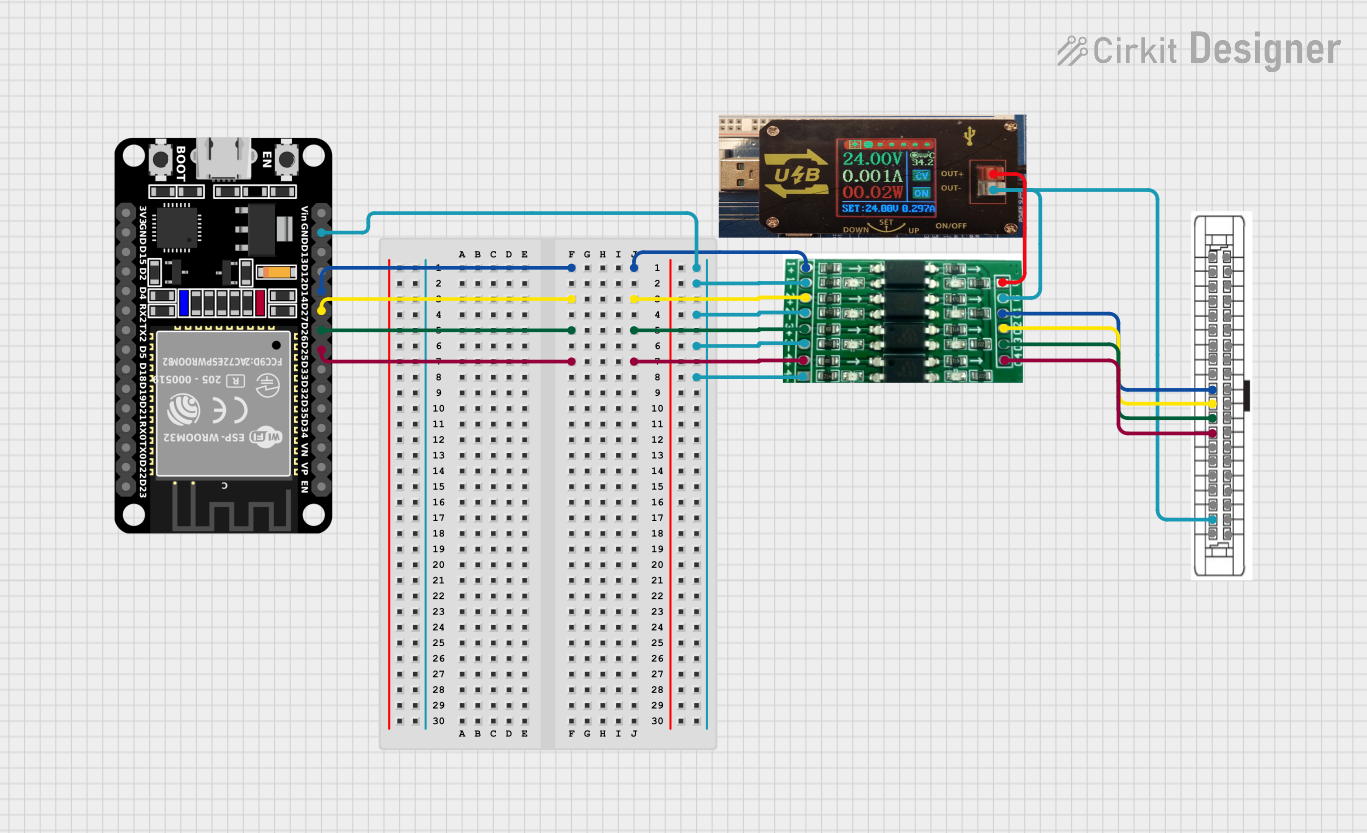
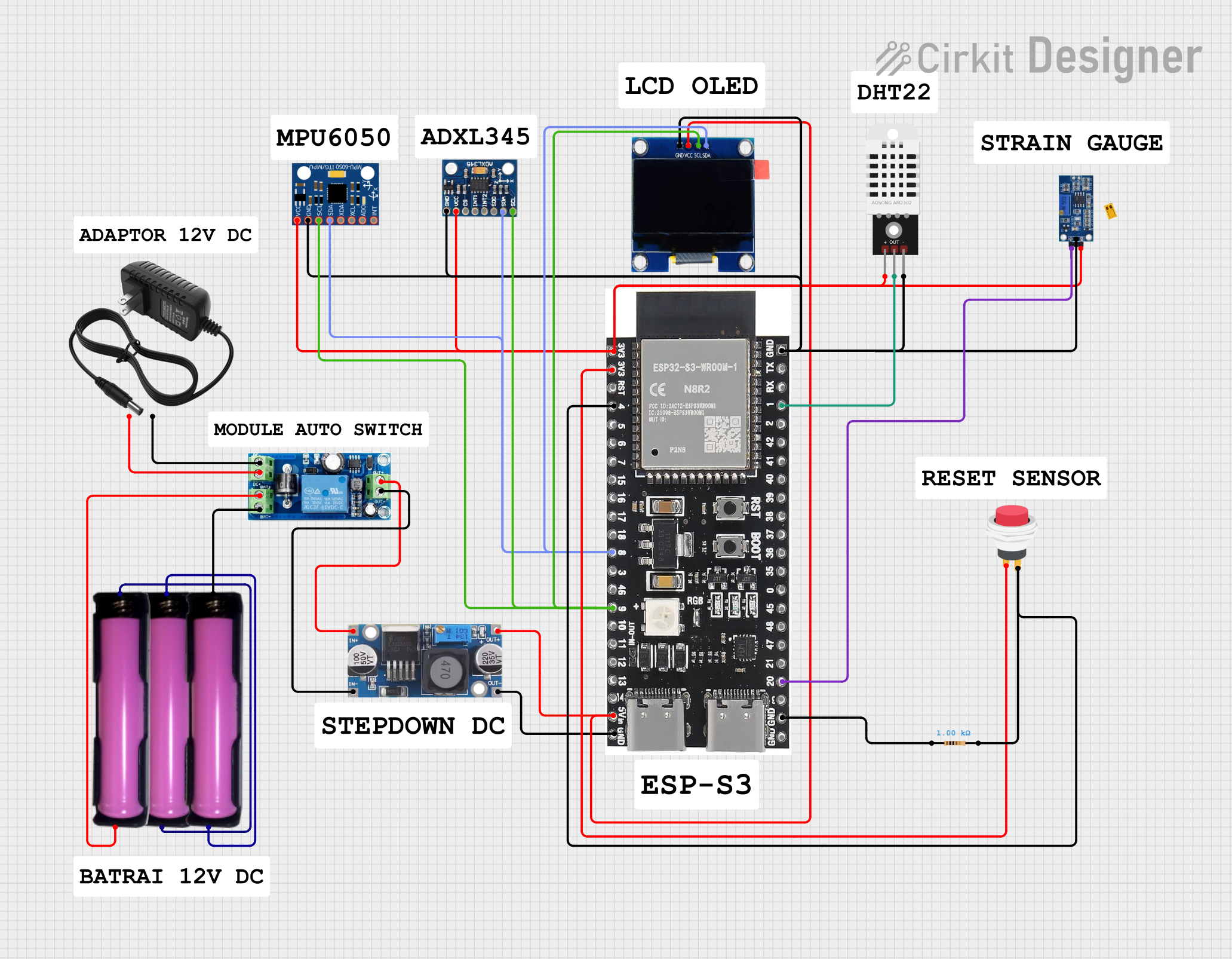
Explore Projects Built with 24_PSU

 Open Project in Cirkit Designer
 Open Project in Cirkit Designer
 Open Project in Cirkit Designer
 Open Project in Cirkit Designer
Explore Projects Built with 24_PSU

 Open Project in Cirkit Designer
 Open Project in Cirkit Designer
 Open Project in Cirkit Designer
 Open Project in Cirkit Designer
Common Applications and Use Cases
- Industrial automation and control systems
- Telecommunication equipment
- LED lighting systems
- Consumer electronics
- Robotics and CNC machines
Technical Specifications
Key Technical Details
- Input Voltage: 100-240V AC, 50/60Hz
- Output Voltage: 24V DC
- Output Current: Specified by model (e.g., 1A, 2.5A, 5A)
- Output Power: Specified by model (e.g., 24W, 60W, 120W)
- Efficiency: >85%
- Operating Temperature: -10°C to +50°C
- Protection: Overvoltage, Overcurrent, Short Circuit, Overtemperature
Pin Configuration and Descriptions
| Pin No. | Description | Notes |
|---|---|---|
| 1 | AC Input L (Live) | Connect to live wire of AC mains |
| 2 | AC Input N (Neutral) | Connect to neutral wire of AC mains |
| 3 | Earth Ground | Connect to grounding system |
| 4 | DC Output (+24V) | Positive output terminal |
| 5 | DC Output (GND) | Ground or negative output terminal |
Usage Instructions
How to Use the Component in a Circuit
Connecting AC Input:
- Ensure the PSU is disconnected from the mains supply.
- Connect the live wire (L) to Pin 1 and the neutral wire (N) to Pin 2.
- Connect the earth ground wire to Pin 3 for safety.
Connecting DC Output:
- Connect the positive terminal of your device to Pin 4 (+24V).
- Connect the ground terminal of your device to Pin 5 (GND).
Powering On:
- Once all connections are secure, plug the PSU into the mains supply.
- Verify the output voltage with a multimeter before connecting sensitive devices.
Important Considerations and Best Practices
- Always disconnect the PSU from the mains supply before making or altering connections.
- Ensure the total load does not exceed the rated output current of the PSU.
- Use appropriate wire gauge for AC input and DC output to handle the current without overheating.
- Install the PSU in a location with adequate ventilation to prevent overheating.
- Do not expose the PSU to moisture or water.
Troubleshooting and FAQs
Common Issues Users Might Face
No Output Voltage:
- Check AC mains connection for proper voltage.
- Verify that the PSU is switched on and the indicator light (if present) is lit.
- Inspect for blown fuses or tripped circuit breakers inside the PSU.
Output Voltage Fluctuates:
- Ensure that the load does not exceed the PSU's rated current.
- Check for loose connections at the output terminals.
- Verify that the PSU is not overheating due to inadequate ventilation or high ambient temperature.
PSU Overheating:
- Reduce the load on the PSU if it exceeds the rated specifications.
- Improve ventilation around the PSU or install a cooling fan.
Solutions and Tips for Troubleshooting
- Always start by checking the input power and connections.
- Use a multimeter to measure the output voltage and ensure it is within the specified range.
- If the PSU has an adjustable output, check that it is set correctly.
- Replace the PSU if it shows signs of damage or if the protection features have been triggered repeatedly.
FAQs
Q: Can I use this PSU with devices that require less than 24V? A: No, this PSU provides a fixed 24V output. Use a step-down converter for devices requiring lower voltages.
Q: Is it safe to use this PSU in outdoor environments? A: Unless specified by the manufacturer, this PSU is designed for indoor use. Outdoor use requires a PSU with appropriate environmental protection ratings.
Q: What should I do if the PSU makes a loud noise or emits a burning smell? A: Immediately disconnect the PSU from the mains supply and do not use it. This could indicate a serious fault.
Q: Can I connect multiple devices to this PSU? A: Yes, as long as the combined current draw does not exceed the PSU's rated output current.
Q: How can I adjust the output voltage of the PSU? A: This model of PSU provides a fixed output voltage. If you need an adjustable voltage, consider a PSU with that feature or use an additional voltage regulator.
For any further assistance or technical support, please contact the manufacturer or your local distributor.