Introduction
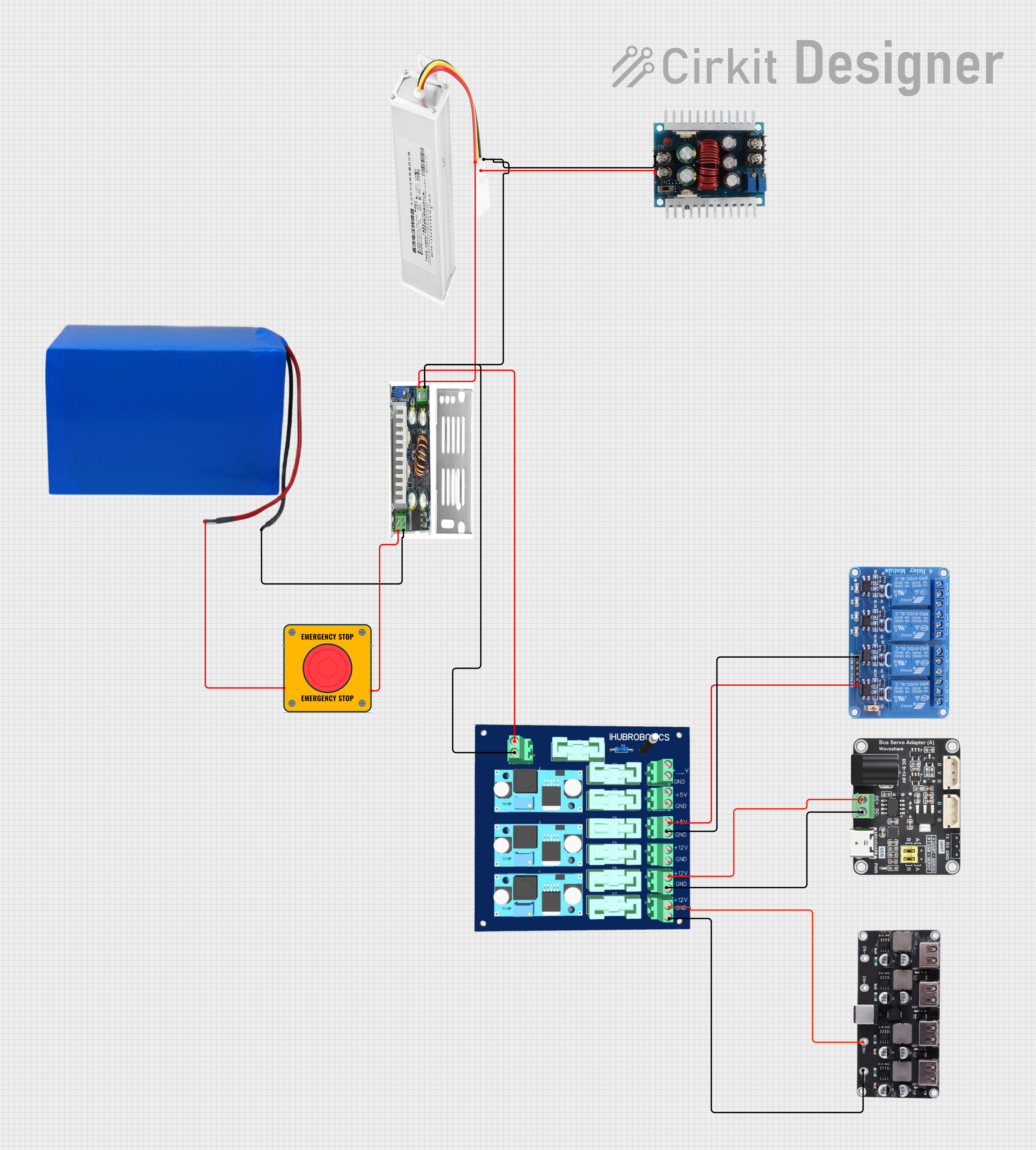
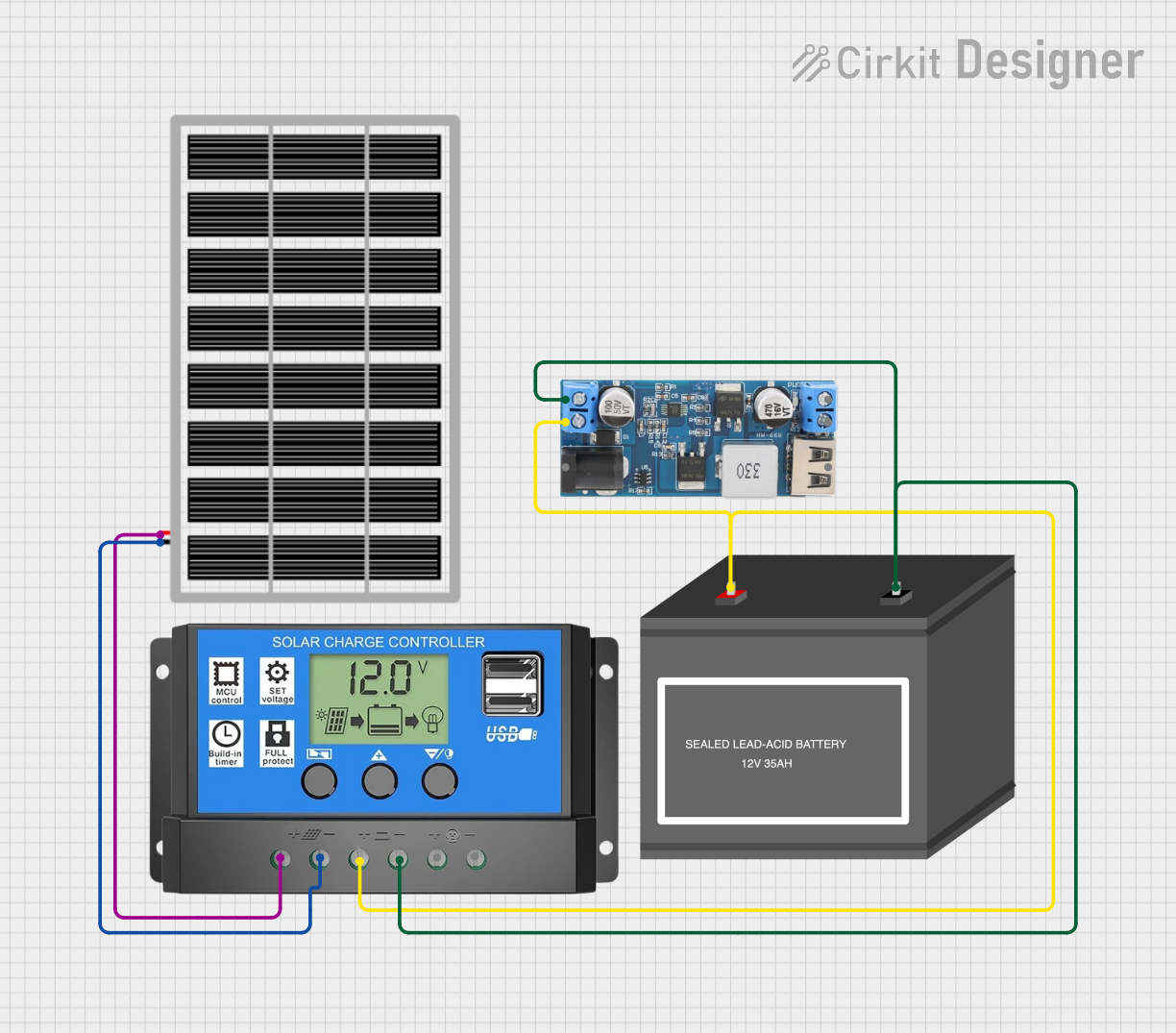
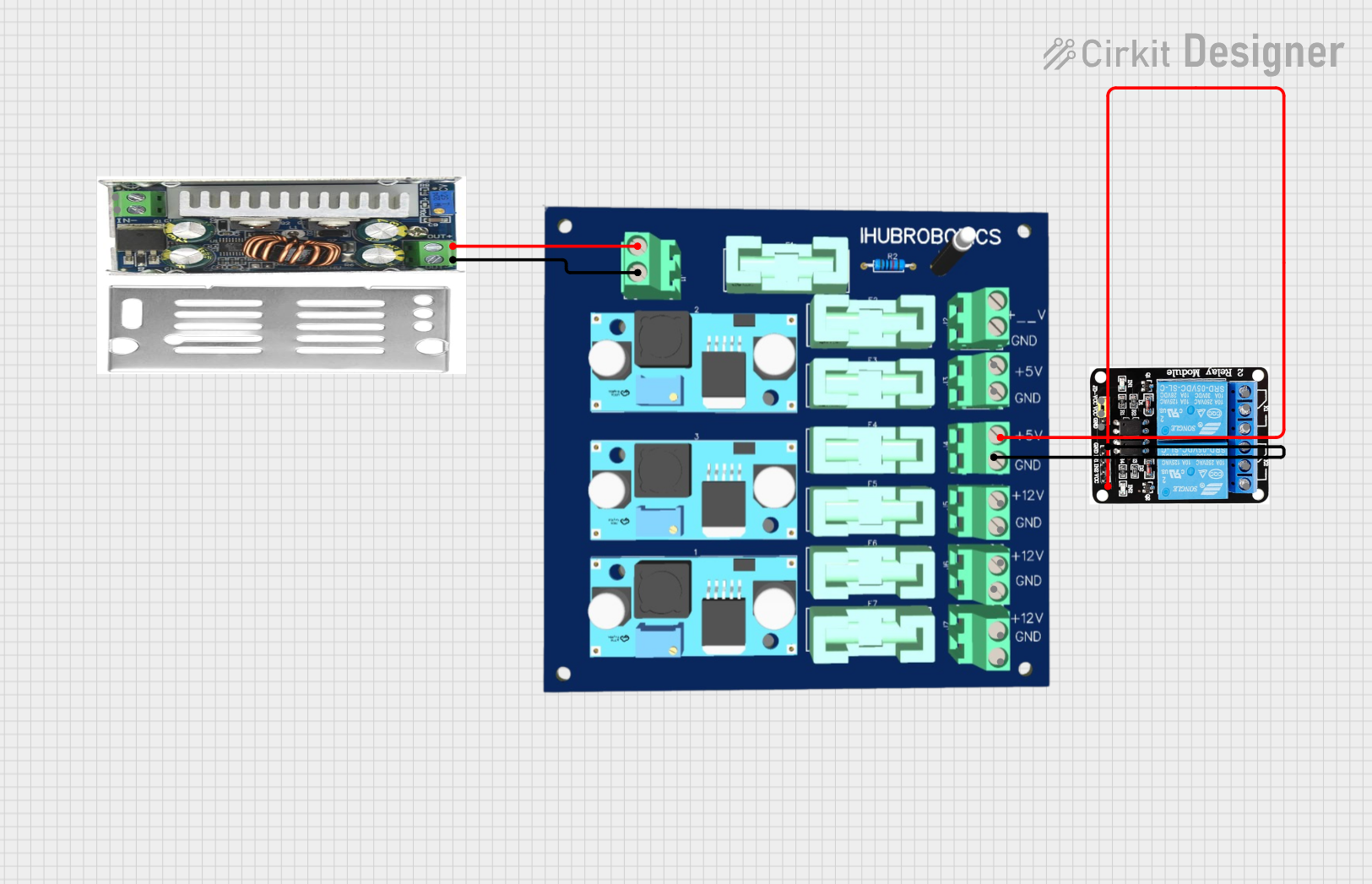
The Module 12V to 5V is a voltage regulator designed to convert a 12V input to a stable 5V output. This module is essential for powering devices that require a 5V supply from a 12V source, such as microcontrollers, sensors, and other low-voltage electronics. Its compact design and high efficiency make it a popular choice for various applications, including automotive electronics, DIY projects, and embedded systems.
Technical Specifications
Key Technical Details
Pin Configuration and Descriptions
Usage Instructions
How to Use the Component in a Circuit
Connect the Input Voltage:
- Connect the VIN pin to the 12V power source.
- Ensure that the power source can supply sufficient current for your application.
Connect the Ground:
- Connect the GND pin to the ground of your circuit.
Connect the Output Voltage:
- Connect the VOUT pin to the device or circuit that requires a 5V supply.
Important Considerations and Best Practices
- Heat Dissipation: Ensure adequate ventilation or heat sinking if the module is used at high currents to prevent overheating.
- Input Voltage Range: While the typical input voltage is 12V, check the module's datasheet for the acceptable input voltage range to avoid damage.
- Polarity: Double-check the polarity of the connections to prevent damage to the module and connected devices.
- Load Requirements: Ensure that the connected load does not exceed the maximum output current rating of the module.
Example Circuit with Arduino UNO
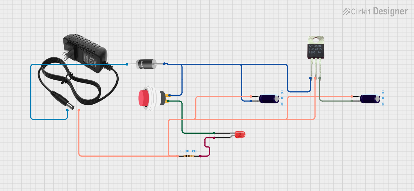
Below is an example of how to use the Module 12V to 5V to power an Arduino UNO:
Circuit Diagram
12V Power Source
   |
   |----> VIN (Module 12V to 5V)
   |
   |----> GND (Module 12V to 5V)

Module 12V to 5V
   |
   |----> VOUT (5V) ----> 5V Pin (Arduino UNO)
   |
   |----> GND ----> GND Pin (Arduino UNO)
Sample Code
// This example code demonstrates a simple blink program for Arduino UNO
// powered by the Module 12V to 5V voltage regulator.

void setup() {
  // Initialize the digital pin LED_BUILTIN as an output.
  pinMode(LED_BUILTIN, OUTPUT);
}

void loop() {
  // Turn the LED on (HIGH is the voltage level)
  digitalWrite(LED_BUILTIN, HIGH);
  // Wait for a second
  delay(1000);
  // Turn the LED off by making the voltage LOW
  digitalWrite(LED_BUILTIN, LOW);
  // Wait for a second
  delay(1000);
}
Troubleshooting and FAQs
Common Issues Users Might Face
No Output Voltage:
- Solution: Check the input voltage and ensure it is within the acceptable range. Verify all connections and ensure correct polarity.
Overheating:
- Solution: Ensure adequate ventilation or use a heat sink. Check if the load current exceeds the module's maximum rating.
Fluctuating Output Voltage:
- Solution: Verify the stability of the input voltage. Ensure that the load is within the module's specifications.
FAQs
Q1: Can I use this module with a 24V input?
- A1: No, the module is designed for a typical input of 12V. Using a higher input voltage may damage the module.
Q2: What is the maximum current this module can supply?
- A2: The module can supply up to 3A of current.
Q3: Can I use this module to power a Raspberry Pi?
- A3: Yes, the 5V output can be used to power a Raspberry Pi, but ensure the current requirements are met.
Q4: How do I know if the module is overheating?
- A4: If the module becomes too hot to touch or if the output voltage drops, it may be overheating. Ensure proper cooling.
By following this documentation, users can effectively utilize the Module 12V to 5V voltage regulator in their projects, ensuring reliable and stable power conversion.


 Open Project in Cirkit Designer