How to Use V60A 14S: Examples, Pinouts, and Specs
Introduction
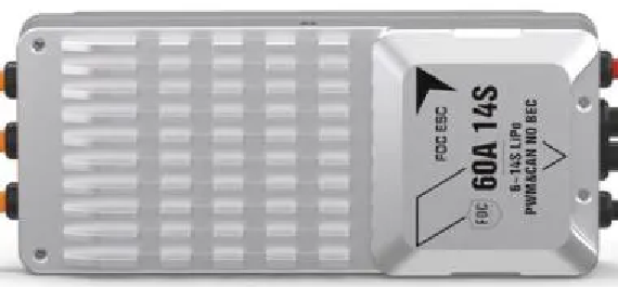
The V60A 14S is a high-performance Battery Management System (BMS) manufactured by T-Motor. It is specifically designed for 14-series lithium-ion battery packs, offering advanced features such as cell balancing, over-voltage protection, and temperature monitoring. This BMS ensures the safe and efficient operation of battery packs in demanding applications.
Explore Projects Built with V60A 14S


Explore Projects Built with V60A 14S
Common Applications
- Electric vehicles (e-bikes, e-scooters, drones)
- Renewable energy storage systems
- Robotics and industrial automation
- High-capacity portable power stations
The V60A 14S is ideal for applications requiring reliable battery management to maximize performance and lifespan.
Technical Specifications
Key Technical Details
| Parameter | Value |
|---|---|
| Supported Battery Type | Lithium-ion (14-series) |
| Maximum Continuous Current | 60A |
| Input Voltage Range | 48V - 60V |
| Cell Balancing Current | 50mA |
| Over-voltage Protection | 4.25V per cell |
| Under-voltage Protection | 2.8V per cell |
| Temperature Monitoring | Yes (NTC thermistor support) |
| Communication Interface | UART |
| Dimensions | 120mm x 80mm x 15mm |
| Weight | 150g |
Pin Configuration and Descriptions
The V60A 14S features a multi-pin connector for interfacing with the battery pack and external systems. Below is the pin configuration:
| Pin Number | Label | Description |
|---|---|---|
| 1 | B- | Battery negative terminal |
| 2 | B+ | Battery positive terminal |
| 3 | P- | Load/charger negative terminal |
| 4 | P+ | Load/charger positive terminal |
| 5 | NTC | Temperature sensor input (NTC thermistor) |
| 6 | UART_TX | UART transmit pin for communication |
| 7 | UART_RX | UART receive pin for communication |
| 8-21 | B1-B14 | Individual cell connections (B1 = lowest cell) |
Usage Instructions
How to Use the V60A 14S in a Circuit
Connect the Battery Pack:
- Connect the negative terminal of the battery pack to the B- pin.
- Connect the positive terminal of the battery pack to the B+ pin.
- Ensure that each cell in the 14-series pack is connected to the corresponding B1-B14 pins.
Connect the Load and Charger:
- Connect the load's negative terminal to the P- pin and the positive terminal to the P+ pin.
- Similarly, connect the charger to the P- and P+ pins.
Temperature Monitoring:
- Attach an NTC thermistor to the NTC pin for real-time temperature monitoring.
Communication:
- Use the UART_TX and UART_RX pins to interface with a microcontroller or PC for monitoring and configuration.
Important Considerations
- Voltage Matching: Ensure the battery pack voltage matches the BMS's supported range (48V - 60V).
- Cell Balancing: The BMS automatically balances cells during charging. Avoid bypassing this feature.
- Heat Dissipation: Install the BMS in a well-ventilated area to prevent overheating.
- Wiring Order: Always connect the battery pack before connecting the load or charger to avoid damage.
Example: Connecting to an Arduino UNO
The V60A 14S can communicate with an Arduino UNO via UART. Below is an example code snippet for reading data from the BMS:
#include <SoftwareSerial.h>

// Define UART pins for communication with the BMS
#define RX_PIN 10  // Arduino pin connected to BMS UART_TX
#define TX_PIN 11  // Arduino pin connected to BMS UART_RX

SoftwareSerial BMS(RX_PIN, TX_PIN); // Initialize software serial

void setup() {
  Serial.begin(9600);       // Start serial monitor
  BMS.begin(9600);          // Start communication with BMS
  Serial.println("BMS Communication Initialized");
}

void loop() {
  if (BMS.available()) {
    // Read data from the BMS and print it to the serial monitor
    String data = BMS.readString();
    Serial.println("BMS Data: " + data);
  }
  delay(1000); // Wait 1 second before the next read
}
Note: Ensure the BMS's UART baud rate matches the Arduino's configuration (default: 9600).
Troubleshooting and FAQs
Common Issues and Solutions
BMS Not Powering On:
- Cause: Incorrect wiring or insufficient battery voltage.
- Solution: Verify all connections and ensure the battery pack voltage is within the supported range (48V - 60V).
Over-voltage or Under-voltage Errors:
- Cause: One or more cells exceed the voltage limits.
- Solution: Check individual cell voltages and replace any faulty cells.
Excessive Heat:
- Cause: High current draw or poor ventilation.
- Solution: Reduce the load current or improve airflow around the BMS.
No Communication via UART:
- Cause: Incorrect UART wiring or mismatched baud rate.
- Solution: Verify the UART connections and ensure the baud rate is set to 9600.
FAQs
Q1: Can the V60A 14S be used with other battery chemistries?
A1: No, the V60A 14S is specifically designed for 14-series lithium-ion battery packs.
Q2: Does the BMS support parallel battery configurations?
A2: Yes, but ensure each parallel pack is balanced and connected properly.
Q3: How do I reset the BMS after a protection event?
A3: Disconnect the load and charger, then reconnect the battery pack to reset the BMS.
Q4: Can I use the BMS without a temperature sensor?
A4: While possible, it is not recommended as temperature monitoring is critical for safety.
This concludes the documentation for the T-Motor V60A 14S Battery Management System. For further assistance, refer to the manufacturer's user manual or contact technical support.