How to Use RTU RELAY 8CH: Examples, Pinouts, and Specs
Introduction
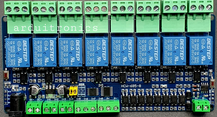
The RTU RELAY 8CH is an 8-channel remote terminal unit (RTU) relay module designed for controlling multiple devices or circuits remotely. It is widely used in industrial automation, home automation, and monitoring systems. This component allows users to control up to eight independent relays, making it ideal for applications requiring centralized control of multiple devices such as lights, motors, pumps, or other electrical loads.
Explore Projects Built with RTU RELAY 8CH


Explore Projects Built with RTU RELAY 8CH
Common Applications
- Industrial automation systems
- Home automation (e.g., controlling lights, fans, or appliances)
- Remote monitoring and control of electrical equipment
- IoT-based smart systems
- Security and access control systems
Technical Specifications
The RTU RELAY 8CH module is designed to handle a variety of electrical loads and is compatible with microcontrollers, PLCs, and other control systems.
Key Technical Details
| Parameter | Specification |
|---|---|
| Operating Voltage | 5V DC / 12V DC (model-dependent) |
| Relay Channels | 8 |
| Relay Type | SPDT (Single Pole Double Throw) |
| Maximum Load (per relay) | 10A @ 250V AC or 10A @ 30V DC |
| Control Signal Voltage | 3.3V or 5V logic (TTL compatible) |
| Isolation | Optocoupler isolation for each channel |
| Communication Interface | RS485 (Modbus RTU protocol) |
| Dimensions | 135mm x 70mm x 20mm |
| Mounting | Screw holes for panel or DIN rail |
Pin Configuration and Descriptions
Power and Communication Pins
| Pin Name | Description |
|---|---|
| VCC | Power supply input (5V or 12V, depending on model) |
| GND | Ground connection |
| A+ | RS485 communication line (positive) |
| B- | RS485 communication line (negative) |
Relay Output Terminals
Each relay channel has three terminals: NO (Normally Open), NC (Normally Closed), and COM (Common). The table below describes the functionality of these terminals.
| Terminal Name | Description |
|---|---|
| NO | Normally open terminal; connected to COM when relay is activated |
| NC | Normally closed terminal; connected to COM when relay is deactivated |
| COM | Common terminal shared between NO and NC |
Usage Instructions
How to Use the RTU RELAY 8CH in a Circuit
- Power the Module: Connect the VCC and GND pins to a 5V or 12V DC power supply, depending on the module version.
- Connect the RS485 Interface: Use the A+ and B- pins to connect the module to an RS485 communication bus. Ensure proper termination resistors are used for long-distance communication.
- Connect the Load: For each relay channel, connect the load to the NO, NC, and COM terminals as required:
- Use NO and COM for devices that should be off by default and turn on when the relay is activated.
- Use NC and COM for devices that should be on by default and turn off when the relay is activated.
- Control the Relays: Send Modbus RTU commands via the RS485 interface to control the relays. Each relay can be independently activated or deactivated.
Important Considerations and Best Practices
- Isolation: Ensure proper electrical isolation between the control circuit and the load to prevent damage to the module or connected devices.
- Load Ratings: Do not exceed the maximum load ratings of 10A @ 250V AC or 10A @ 30V DC per relay.
- RS485 Termination: For reliable communication, use a 120-ohm termination resistor at the end of the RS485 bus.
- Power Supply: Use a stable and regulated power supply to avoid voltage fluctuations that could affect relay operation.
Example: Controlling the RTU RELAY 8CH with Arduino UNO
Below is an example of how to control the RTU RELAY 8CH using an Arduino UNO and the Modbus RTU protocol.
#include <ModbusMaster.h> // Include the ModbusMaster library

ModbusMaster node; // Create a ModbusMaster object

void setup() {
  Serial.begin(9600); // Initialize serial communication
  node.begin(1, Serial); // Set Modbus slave ID to 1 and use Serial for communication
}

void loop() {
  // Activate relay 1 (coil 0)
  uint8_t result = node.writeSingleCoil(0, 1);
  if (result == node.ku8MBSuccess) {
    Serial.println("Relay 1 activated");
  } else {
    Serial.println("Failed to activate Relay 1");
  }

  delay(1000); // Wait for 1 second

  // Deactivate relay 1 (coil 0)
  result = node.writeSingleCoil(0, 0);
  if (result == node.ku8MBSuccess) {
    Serial.println("Relay 1 deactivated");
  } else {
    Serial.println("Failed to deactivate Relay 1");
  }

  delay(1000); // Wait for 1 second
}
Notes on the Code
- The
ModbusMasterlibrary is used to communicate with the RTU RELAY 8CH via the RS485 interface. - Replace
0inwriteSingleCoil(0, 1)with the appropriate coil address for other relays (e.g.,1for relay 2,2for relay 3, etc.). - Ensure the RS485 transceiver module is connected between the Arduino and the RTU RELAY 8CH.
Troubleshooting and FAQs
Common Issues and Solutions
Relays Not Activating
- Cause: Incorrect RS485 wiring or communication settings.
- Solution: Verify the A+ and B- connections and ensure the baud rate and Modbus slave ID match the module's configuration.
Communication Errors
- Cause: Missing or incorrect termination resistors on the RS485 bus.
- Solution: Add a 120-ohm termination resistor at the end of the RS485 bus.
Relay Flickering
- Cause: Unstable power supply or excessive load.
- Solution: Use a regulated power supply and ensure the load does not exceed the relay's maximum rating.
Overheating
- Cause: Continuous operation near maximum load capacity.
- Solution: Reduce the load or provide adequate cooling for the module.
FAQs
Q: Can I use the RTU RELAY 8CH with a 3.3V microcontroller?
A: Yes, the module is TTL compatible and can be controlled with 3.3V or 5V logic levels.
Q: How do I change the Modbus slave ID?
A: Refer to the module's user manual for instructions on configuring the Modbus slave ID using DIP switches or software.
Q: Can I control multiple RTU RELAY 8CH modules on the same RS485 bus?
A: Yes, you can connect multiple modules by assigning each a unique Modbus slave ID.