How to Use LED: Two Pin (white): Examples, Pinouts, and Specs
Introduction
A white LED (Light-Emitting Diode) with two pins is a semiconductor device that emits white light when an electric current flows through it. LEDs are widely used due to their energy efficiency, long life, and compact size. Common applications include indicator lights, backlighting, automotive lighting, and general illumination.
Explore Projects Built with LED: Two Pin (white)

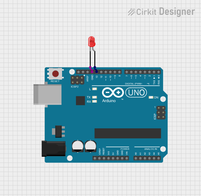
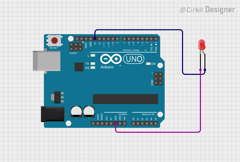
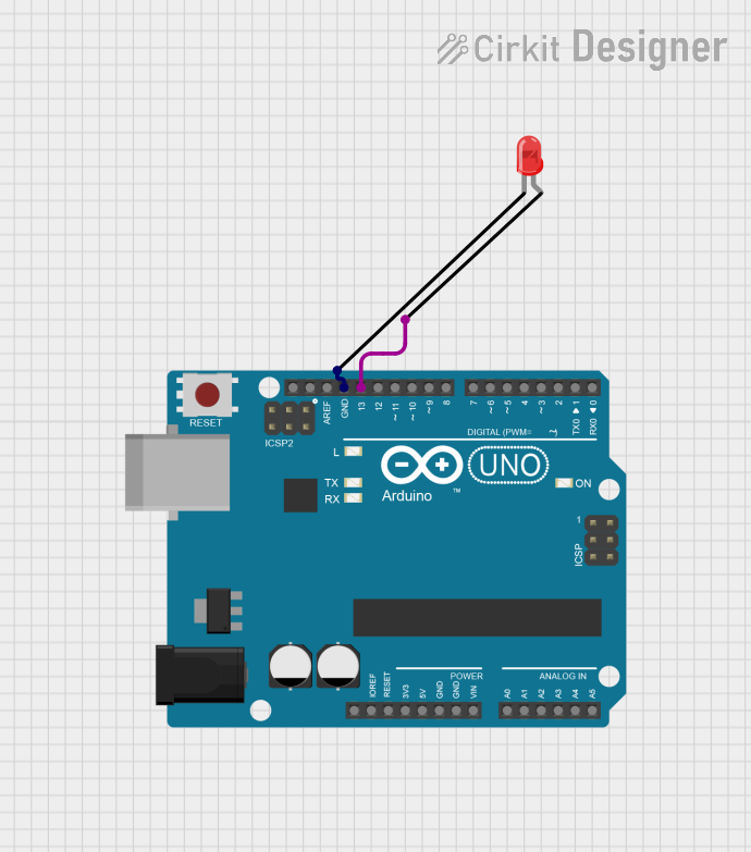
Explore Projects Built with LED: Two Pin (white)
Technical Specifications
Key Technical Details
- Forward Voltage (Vf): Typically 3.0V to 3.4V
- Forward Current (If): Recommended 20mA (max. 30mA)
- Luminous Intensity: Varies by specific model, often around 6000-8000 mcd
- Viewing Angle: Typically 120 degrees
- Color Temperature: Typically 5000K to 10000K (cool white)
Pin Configuration and Descriptions
| Pin Number | Name | Description |
|---|---|---|
| 1 | Anode (+) | Connects to the positive supply voltage |
| 2 | Cathode (-) | Connects to the ground (0V) |
Usage Instructions
Connecting the LED to a Circuit
- Identify the Pins: The longer pin is usually the anode (+), and the shorter pin is the cathode (-).
- Current Limiting Resistor: Always use a current limiting resistor in series with the LED to prevent it from burning out. The value of the resistor can be calculated using Ohm's law:
R = (Vsupply - Vf) / If. - Polarity: Ensure correct polarity when connecting the LED. Reversing the polarity may damage the LED.
- Soldering: Use a heat sink or be quick when soldering to prevent heat damage to the LED.
Best Practices
- Avoid exceeding the maximum forward current and voltage ratings.
- Use pulse width modulation (PWM) for dimming to maintain the LED's lifespan.
- Consider heat dissipation in high-power applications.
Example Circuit with Arduino UNO
// Define the LED pin
const int ledPin = 13; // Most Arduino UNO boards have an LED on pin 13

void setup() {
  // Set the LED pin as an output
  pinMode(ledPin, OUTPUT);
}

void loop() {
  // Turn the LED on
  digitalWrite(ledPin, HIGH);
  delay(1000); // Wait for 1 second
  // Turn the LED off
  digitalWrite(ledPin, LOW);
  delay(1000); // Wait for 1 second
}
Troubleshooting and FAQs
Common Issues
- LED Not Lighting Up: Check the polarity of the LED and the connection of the current limiting resistor.
- LED Burnt Out: Ensure the current through the LED does not exceed the maximum rating.
- Dim LED: Verify that the power supply voltage is adequate and the current limiting resistor is correctly calculated.
Solutions and Tips
- Polarity Check: Use a multimeter to verify the anode and cathode if the LED's pins are trimmed.
- Resistor Value: Recalculate the resistor value if the supply voltage changes.
- Heat Management: In high-power applications, use appropriate heat sinks to manage heat dissipation.
FAQs
Q: Can I connect multiple LEDs in series? A: Yes, but ensure the power supply voltage is high enough to provide the forward voltage for all LEDs combined.
Q: How do I calculate the resistor value for a 5V Arduino pin? A: For a typical white LED with Vf = 3.2V and If = 20mA, R = (5V - 3.2V) / 0.02A = 90Ω. Choose the nearest standard resistor value, which is 100Ω.
Q: Can I use a 9V battery to power the LED? A: Yes, but you must recalculate the current limiting resistor value to accommodate the higher voltage.
Q: Is it possible to dim the LED? A: Yes, you can use PWM on an Arduino to dim the LED by changing the duty cycle of the output signal.