
How to Use ZUNE_CONNECTOR_MALE: Examples, Pinouts, and Specs
 Design with ZUNE_CONNECTOR_MALE in Cirkit Designer
Introduction
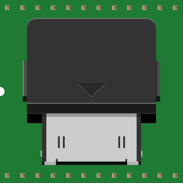
The ZUNE_CONNECTOR_MALE, manufactured by Microsoft (Part ID: Zune male connector), is a proprietary male connector designed for interfacing Zune devices with various peripherals. This connector facilitates data transfer, charging, and communication between Zune devices and compatible accessories. Its unique pin configuration ensures reliable performance and compatibility with Zune-specific hardware.
Explore Projects Built with ZUNE_CONNECTOR_MALE
 Open Project in Cirkit Designer
 Open Project in Cirkit Designer
 Open Project in Cirkit Designer
 Open Project in Cirkit Designer
Explore Projects Built with ZUNE_CONNECTOR_MALE
Open Project in Cirkit DesignerOpen Project in Cirkit DesignerOpen Project in Cirkit DesignerOpen Project in Cirkit DesignerCommon Applications and Use Cases
- Data Transfer: Syncing Zune devices with computers or other data storage systems.
- Charging: Providing power to Zune devices via compatible chargers or docking stations.
- Peripheral Connectivity: Connecting Zune devices to audio systems, video output devices, or other accessories.
Technical Specifications
Key Technical Details
| Parameter | Specification |
|---|---|
| Manufacturer | Microsoft |
| Part ID | Zune male connector |
| Number of Pins | 24 |
| Voltage Rating | 5V DC (typical for USB power) |
| Current Rating | 1A (maximum) |
| Connector Type | Male |
| Compatibility | Zune devices and peripherals |
| Dimensions | 30mm x 10mm x 5mm (approximate) |
Pin Configuration and Descriptions
The ZUNE_CONNECTOR_MALE features a 24-pin layout, with specific pins designated for power, ground, data transfer, and accessory control. Below is the pin configuration:
| Pin Number | Function | Description |
|---|---|---|
| 1 | VBUS (Power) | Provides 5V DC power for charging the device. |
| 2 | D- (Data Negative) | USB data line for data transfer (negative). |
| 3 | D+ (Data Positive) | USB data line for data transfer (positive). |
| 4 | GND (Ground) | Ground connection for power and data. |
| 5-8 | Reserved | Reserved for proprietary functions. |
| 9-16 | Accessory Control | Used for communication with Zune peripherals. |
| 17-24 | Audio/Video Output | Outputs audio and video signals to accessories. |
Note: Pins 5-24 are proprietary and may vary depending on the specific Zune device or accessory.
Usage Instructions
How to Use the Component in a Circuit
- Identify the Pinout: Refer to the pin configuration table above to correctly identify the pins for power, ground, and data transfer.
- Connect Power and Ground: Ensure that the VBUS (Pin 1) is connected to a 5V DC power source and GND (Pin 4) is connected to the circuit ground.
- Data Transfer: Use Pins 2 (D-) and 3 (D+) for USB data communication. Ensure proper polarity and shielding to avoid data corruption.
- Peripheral Connections: For audio, video, or accessory control, connect the appropriate pins (Pins 9-24) as per the peripheral's specifications.
Important Considerations and Best Practices
- Voltage Regulation: Ensure the power supply provides a stable 5V DC to avoid damaging the Zune device.
- Pin Protection: Avoid shorting any pins, especially the proprietary ones, as this may damage the connector or the connected device.
- Cable Quality: Use high-quality cables to ensure reliable data transfer and charging performance.
- Compatibility: Verify that the peripheral or accessory is designed for Zune devices to ensure proper functionality.
Example: Connecting to an Arduino UNO
The ZUNE_CONNECTOR_MALE can be used with an Arduino UNO for basic data communication. Below is an example code snippet for reading data from the connector:
// Example: Reading data from ZUNE_CONNECTOR_MALE using Arduino UNO
// Connect D+ (Pin 3) to Arduino digital pin 2
// Connect D- (Pin 2) to Arduino digital pin 3
// Ensure GND (Pin 4) is connected to Arduino GND

#define DATA_POSITIVE_PIN 2  // D+ connected to digital pin 2
#define DATA_NEGATIVE_PIN 3  // D- connected to digital pin 3

void setup() {
  pinMode(DATA_POSITIVE_PIN, INPUT);  // Set D+ as input
  pinMode(DATA_NEGATIVE_PIN, INPUT);  // Set D- as input
  Serial.begin(9600);  // Initialize serial communication
}

void loop() {
  int dataPositive = digitalRead(DATA_POSITIVE_PIN);  // Read D+ signal
  int dataNegative = digitalRead(DATA_NEGATIVE_PIN);  // Read D- signal

  // Print the data signals to the Serial Monitor
  Serial.print("D+: ");
  Serial.print(dataPositive);
  Serial.print(" | D-: ");
  Serial.println(dataNegative);

  delay(500);  // Delay for readability
}
Note: This example demonstrates basic signal reading. For full USB communication, additional hardware and libraries are required.
Troubleshooting and FAQs
Common Issues and Solutions
No Power to the Device
- Cause: Incorrect connection to VBUS or GND pins.
- Solution: Verify the power supply and ensure proper connections to Pins 1 (VBUS) and 4 (GND).
Data Transfer Fails
- Cause: Misconnection of D+ and D- pins or poor cable quality.
- Solution: Check the connections to Pins 2 (D-) and 3 (D+). Use a shielded cable for better signal integrity.
Peripheral Not Recognized
- Cause: Incompatible accessory or incorrect pin connections.
- Solution: Ensure the accessory is designed for Zune devices and verify connections to Pins 9-24.
Overheating
- Cause: Excessive current draw or shorted pins.
- Solution: Limit current to 1A and inspect for short circuits.
FAQs
Q: Can I use the ZUNE_CONNECTOR_MALE with non-Zune devices?
- A: The connector is designed specifically for Zune devices. Compatibility with non-Zune devices is not guaranteed.
Q: What is the maximum cable length for reliable data transfer?
- A: For USB data transfer, the recommended maximum cable length is 5 meters.
Q: Are replacement connectors available?
- A: Yes, replacement connectors can be sourced from authorized Microsoft distributors or third-party vendors.
Q: Can I use this connector for audio output only?
- A: Yes, the connector supports audio output via specific pins (Pins 17-24). Ensure proper wiring to the audio accessory.
This concludes the documentation for the ZUNE_CONNECTOR_MALE. For further assistance, refer to the manufacturer's support resources.