
How to Use DB9 Connector: Examples, Pinouts, and Specs
 Design with DB9 Connector in Cirkit Designer
Introduction
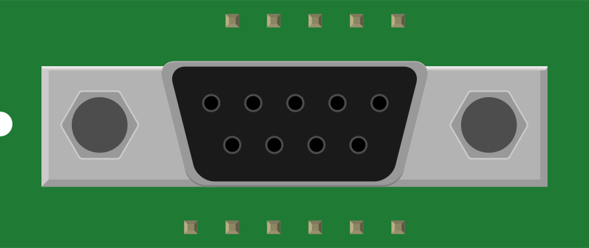
The DB9 connector is a 9-pin D-subminiature connector widely used for serial communication. It is a standard interface for RS-232 communication protocols and is commonly found in devices such as computers, modems, printers, and industrial equipment. The connector is known for its durability and reliability in transmitting data over short distances.
Explore Projects Built with DB9 Connector
 Open Project in Cirkit Designer
 Open Project in Cirkit Designer
 Open Project in Cirkit Designer
 Open Project in Cirkit Designer
Explore Projects Built with DB9 Connector
Open Project in Cirkit DesignerOpen Project in Cirkit DesignerOpen Project in Cirkit DesignerOpen Project in Cirkit DesignerCommon Applications and Use Cases
- Serial communication between computers and peripherals
- Connecting modems, printers, and industrial controllers
- Debugging and programming microcontrollers
- Data acquisition systems
- Legacy hardware interfacing
Technical Specifications
Key Technical Details
- Connector Type: D-subminiature, 9-pin
- Gender: Male (plug) or Female (socket)
- Pin Count: 9
- Communication Protocol: RS-232 (commonly used)
- Voltage Rating: Typically ±12V for RS-232 signals
- Current Rating: Up to 5A (depending on the specific connector model)
- Mounting Style: Panel mount or cable mount
- Material: Metal shell with plastic insulator and gold-plated or tin-plated pins
- Operating Temperature: -55°C to +105°C (varies by manufacturer)
Pin Configuration and Descriptions
The DB9 connector has 9 pins, each with a specific function in RS-232 communication. Below is the standard pinout for a DB9 connector:
| Pin Number | Abbreviation | Function |
|---|---|---|
| 1 | DCD | Data Carrier Detect |
| 2 | RXD | Receive Data |
| 3 | TXD | Transmit Data |
| 4 | DTR | Data Terminal Ready |
| 5 | GND | Signal Ground |
| 6 | DSR | Data Set Ready |
| 7 | RTS | Request to Send |
| 8 | CTS | Clear to Send |
| 9 | RI | Ring Indicator |
Note: The pinout may vary depending on the application or device. Always refer to the device's datasheet for specific configurations.
Usage Instructions
How to Use the DB9 Connector in a Circuit
- Identify the Pinout: Refer to the pin configuration table above to understand the function of each pin.
- Connect the Wires: Solder or crimp the wires to the appropriate pins based on your application. Ensure proper insulation to avoid short circuits.
- Mount the Connector: If using a panel-mount DB9 connector, secure it to the panel using screws. For cable-mounted connectors, use a strain relief to protect the wires.
- Verify Connections: Use a multimeter to check continuity and ensure that the connections are correct.
- Connect to Devices: Plug the DB9 connector into the corresponding port on the device. Tighten the screws on the sides to secure the connection.
Important Considerations and Best Practices
- Signal Levels: Ensure that the voltage levels conform to the RS-232 standard (typically ±12V). Using incorrect voltage levels can damage the connected devices.
- Cable Length: RS-232 communication is designed for short distances (up to 15 meters). For longer distances, consider using a different protocol.
- Shielding: Use shielded cables to minimize electromagnetic interference (EMI), especially in noisy environments.
- Gender Matching: Ensure that the connector's gender (male or female) matches the port on the device.
- Arduino Compatibility: When connecting a DB9 connector to an Arduino, use an RS-232 to TTL converter module to safely interface the voltage levels.
Example: Connecting a DB9 Connector to an Arduino UNO
To interface a DB9 connector with an Arduino UNO, you will need an RS-232 to TTL converter module. Below is an example code snippet for receiving data from a device via the DB9 connector:
#include <SoftwareSerial.h>

// Define RX and TX pins for the RS-232 to TTL converter
SoftwareSerial mySerial(10, 11); // RX = pin 10, TX = pin 11

void setup() {
  Serial.begin(9600); // Start the hardware serial communication
  mySerial.begin(9600); // Start the software serial communication
  Serial.println("DB9 Connector Communication Initialized");
}

void loop() {
  // Check if data is available from the DB9-connected device
  if (mySerial.available()) {
    char receivedChar = mySerial.read(); // Read the incoming character
    Serial.print("Received: ");
    Serial.println(receivedChar); // Print the received character to the Serial Monitor
  }
}
Note: Ensure that the baud rate (9600 in this example) matches the settings of the connected device.
Troubleshooting and FAQs
Common Issues and Solutions
No Data Transmission
- Cause: Incorrect pin connections or mismatched baud rate.
- Solution: Double-check the pinout and ensure the baud rate matches the connected device.
Intermittent Communication
- Cause: Loose connections or EMI.
- Solution: Secure the connector screws and use shielded cables.
Device Not Recognized
- Cause: Incorrect gender or damaged connector.
- Solution: Verify the connector's gender and inspect for physical damage.
Voltage Level Mismatch
- Cause: Directly connecting RS-232 signals to TTL devices.
- Solution: Use an RS-232 to TTL converter module to safely interface the devices.
FAQs
Q: Can I use a DB9 connector for USB communication?
A: No, the DB9 connector is designed for RS-232 communication. For USB, use a USB-to-serial adapter.Q: What is the maximum data rate for a DB9 connector?
A: The maximum data rate depends on the RS-232 standard and cable quality, typically up to 115.2 kbps.Q: Can I use a DB9 connector for power transmission?
A: While the DB9 connector can handle small currents (up to 5A), it is not recommended for power transmission due to its primary design for data communication.Q: How do I identify the pin numbers on a DB9 connector?
A: The pin numbers are usually labeled on the connector. For male connectors, the pins are numbered from left to right, top to bottom when viewed from the front.
By following this documentation, you can effectively use the DB9 connector in your projects and troubleshoot common issues with ease.