How to Use ESP32 38 PINS: Examples, Pinouts, and Specs
Introduction
The ESP32 38 Pins is a versatile microcontroller designed for a wide range of applications, particularly in the Internet of Things (IoT) and embedded systems. It features integrated Wi-Fi and Bluetooth capabilities, making it a powerful choice for wireless communication projects. With 38 GPIO pins, the ESP32 provides extensive input/output functionality, enabling developers to connect various sensors, actuators, and peripherals.
Explore Projects Built with ESP32 38 PINS


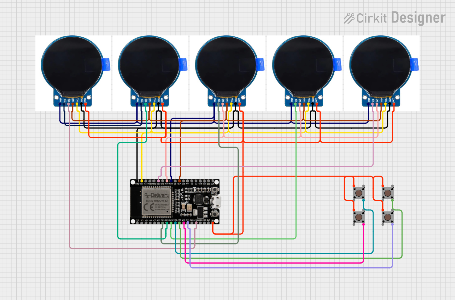

Explore Projects Built with ESP32 38 PINS
Common Applications and Use Cases
- IoT devices and smart home automation
- Wireless sensor networks
- Wearable technology
- Robotics and automation systems
- Data logging and remote monitoring
- Prototyping and educational projects
Technical Specifications
The ESP32 38 Pins microcontroller is packed with features that make it suitable for a variety of applications. Below are its key technical specifications:
Key Technical Details
- Processor: Dual-core Xtensa® 32-bit LX6 microprocessor
- Clock Speed: Up to 240 MHz
- Flash Memory: 4 MB (varies by model)
- SRAM: 520 KB
- Wi-Fi: 802.11 b/g/n (2.4 GHz)
- Bluetooth: v4.2 BR/EDR and BLE
- Operating Voltage: 3.3V
- GPIO Pins: 38 (multipurpose)
- ADC Channels: 18 (12-bit resolution)
- DAC Channels: 2
- PWM Outputs: Multiple
- Communication Protocols: UART, SPI, I2C, I2S, CAN
- Power Consumption: Ultra-low power consumption in deep sleep mode (~10 µA)
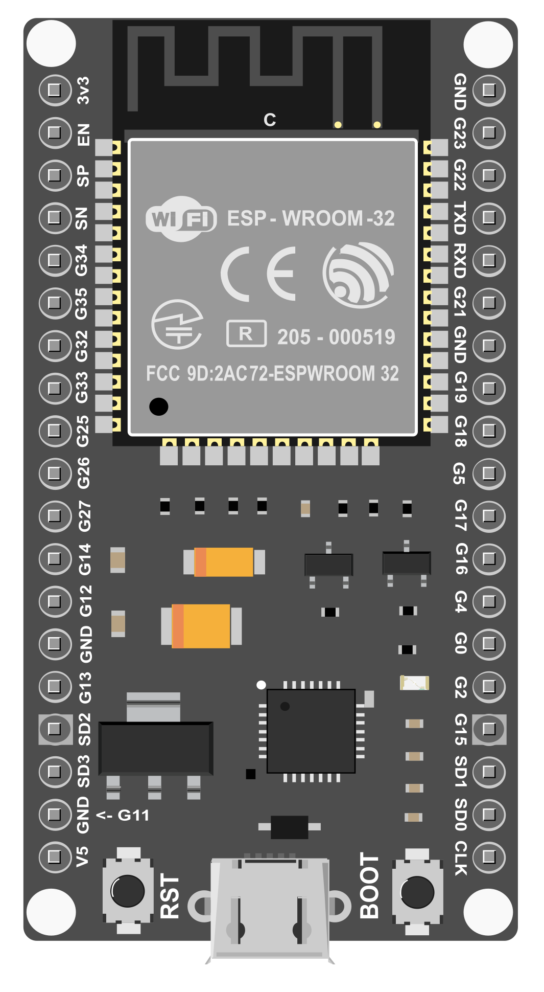
Pin Configuration and Descriptions
The ESP32 38 Pins has a total of 38 GPIO pins, each with specific functions. Below is a table summarizing the pin configuration:
| Pin Number | Pin Name | Function |
|---|---|---|
| 1 | EN | Enable pin (active high) |
| 2 | IO0 | GPIO0, boot mode selection |
| 3 | IO1 (TX0) | GPIO1, UART0 TX |
| 4 | IO2 | GPIO2, ADC, PWM |
| 5 | IO3 (RX0) | GPIO3, UART0 RX |
| 6-11 | IO4-IO9 | GPIO, ADC, PWM |
| 12 | IO10 | GPIO10, ADC, PWM |
| 13-38 | IO11-IO36 | GPIO, ADC, PWM, I2C, SPI, UART |
Note: Some pins have dual or multiplexed functions. Refer to the ESP32 datasheet for detailed pin mappings and restrictions.
Usage Instructions
The ESP32 38 Pins is easy to integrate into a variety of projects. Below are the steps and best practices for using this microcontroller.
How to Use the ESP32 in a Circuit
- Powering the ESP32:
- Supply 3.3V to the
3V3pin. Avoid exceeding this voltage to prevent damage. - Alternatively, use the onboard USB connector for power and programming.
- Supply 3.3V to the
- Connecting Peripherals:
- Use GPIO pins to connect sensors, actuators, or other devices.
- Ensure peripherals operate at 3.3V logic levels to avoid damaging the ESP32.
- Programming the ESP32:
- Install the Arduino IDE or ESP-IDF (Espressif IoT Development Framework).
- Select the appropriate ESP32 board in the IDE settings.
- Connect the ESP32 to your computer via USB and upload your code.
Important Considerations and Best Practices
- GPIO Voltage Levels: The ESP32 operates at 3.3V logic levels. Use level shifters if interfacing with 5V devices.
- Boot Mode: Ensure GPIO0 is pulled low during boot to enter programming mode.
- Power Supply: Use a stable power source to avoid unexpected resets or malfunctions.
- Deep Sleep Mode: Utilize deep sleep mode for battery-powered applications to conserve energy.
Example Code for Arduino UNO Integration
Below is an example of how to blink an LED connected to GPIO2 of the ESP32:
// Example: Blink an LED connected to GPIO2 on the ESP32

#define LED_PIN 2  // Define GPIO2 as the LED pin

void setup() {
  pinMode(LED_PIN, OUTPUT);  // Set GPIO2 as an output pin
}

void loop() {
  digitalWrite(LED_PIN, HIGH);  // Turn the LED on
  delay(1000);                  // Wait for 1 second
  digitalWrite(LED_PIN, LOW);   // Turn the LED off
  delay(1000);                  // Wait for 1 second
}
Tip: Use the onboard LED (if available) for quick testing by connecting to the appropriate GPIO pin.
Troubleshooting and FAQs
Common Issues and Solutions
- ESP32 Not Detected by Computer:
- Ensure the USB cable is functional and supports data transfer.
- Install the correct USB-to-serial driver for your operating system.
- Code Upload Fails:
- Check that GPIO0 is pulled low during programming.
- Verify the correct COM port and board are selected in the IDE.
- Wi-Fi Connection Issues:
- Double-check the SSID and password in your code.
- Ensure the router operates on the 2.4 GHz band (ESP32 does not support 5 GHz).
- Random Resets:
- Use a stable power supply with sufficient current (at least 500 mA).
- Avoid using GPIO pins that conflict with boot mode.
FAQs
Q: Can I use the ESP32 with 5V sensors?
A: The ESP32 operates at 3.3V logic levels. Use a level shifter to safely interface with 5V sensors.
Q: How do I enable Bluetooth on the ESP32?
A: Use the ESP32 Bluetooth library in your code. Refer to the ESP-IDF or Arduino documentation for examples.
Q: What is the maximum current draw of the ESP32?
A: The ESP32 can draw up to 500 mA during peak operation. Ensure your power supply can handle this.
Q: Can I use all 38 GPIO pins simultaneously?
A: Not all GPIO pins are available for general use. Some are reserved for specific functions or have restrictions. Consult the ESP32 datasheet for details.
By following this documentation, you can effectively utilize the ESP32 38 Pins in your projects and troubleshoot common issues with ease.