How to Use ATmega8L: Examples, Pinouts, and Specs
Introduction
The ATmega8L is an 8-bit microcontroller based on the AVR architecture. It features 8 KB of flash memory, 1 KB of SRAM, and 512 bytes of EEPROM, making it a versatile choice for embedded systems. Operating at a maximum clock speed of 16 MHz, the ATmega8L includes a variety of peripherals such as timers, analog-to-digital converters (ADCs), and general-purpose I/O ports. Its low power consumption and robust feature set make it ideal for applications in consumer electronics, industrial automation, robotics, and IoT devices.
Explore Projects Built with ATmega8L


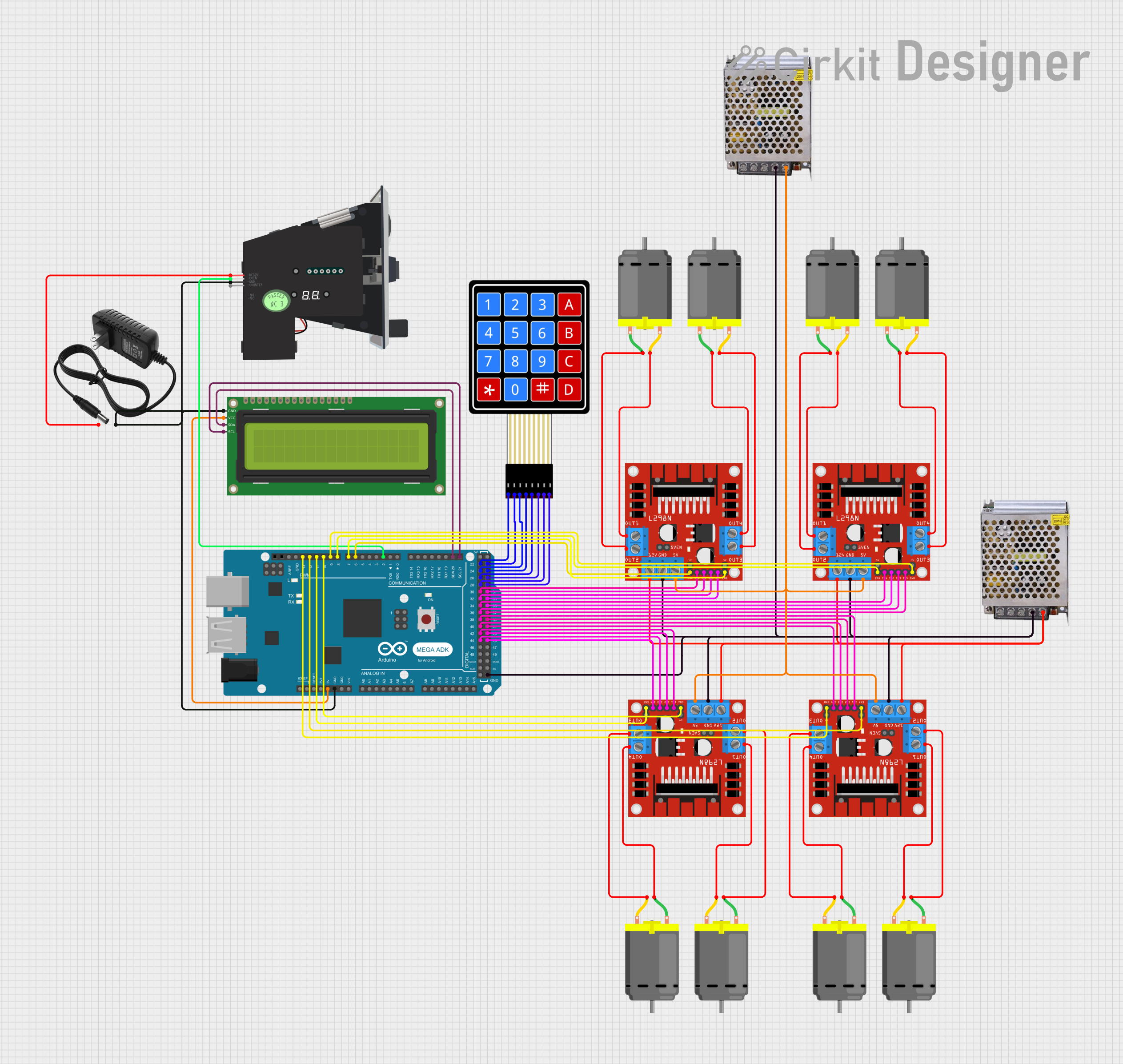
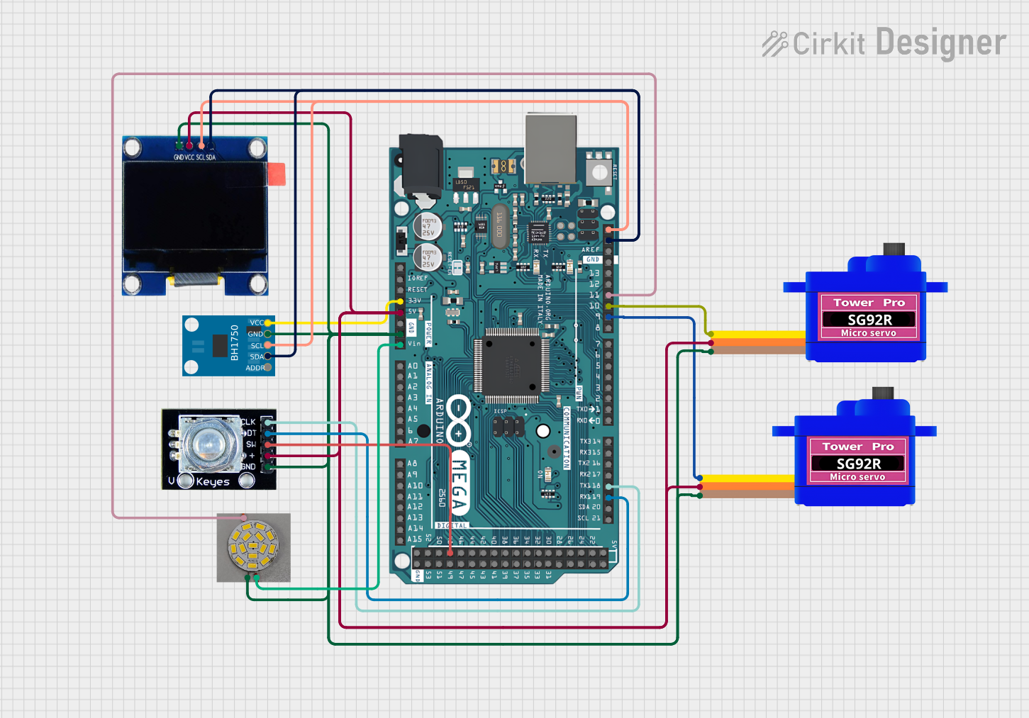
Explore Projects Built with ATmega8L
Common Applications
- Home automation systems
- Robotics and motor control
- Data acquisition and sensor interfacing
- Low-power IoT devices
- Educational and prototyping projects
Technical Specifications
Key Technical Details
| Parameter | Value |
|---|---|
| Architecture | AVR 8-bit |
| Flash Memory | 8 KB |
| SRAM | 1 KB |
| EEPROM | 512 bytes |
| Operating Voltage | 2.7V - 5.5V |
| Maximum Clock Speed | 16 MHz |
| ADC Resolution | 10-bit |
| Number of I/O Pins | 23 |
| Timers | 2 x 8-bit, 1 x 16-bit |
| Communication Interfaces | UART, SPI, I2C (TWI) |
| Power Consumption | Low power, suitable for battery operation |
Pin Configuration and Descriptions
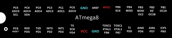
The ATmega8L is available in a 28-pin PDIP package. Below is the pin configuration:
| Pin Number | Pin Name | Description |
|---|---|---|
| 1 | PC6 (RESET) | Reset input (active low) |
| 2 | PD0 (RXD) | UART Receive Data |
| 3 | PD1 (TXD) | UART Transmit Data |
| 4 | PD2 | External Interrupt 0 (INT0) |
| 5 | PD3 | External Interrupt 1 (INT1) |
| 6 | PD4 | General-purpose I/O |
| 7 | VCC | Power supply voltage |
| 8 | GND | Ground |
| 9 | PB6 (XTAL1) | External clock input |
| 10 | PB7 (XTAL2) | External clock output |
| 11-28 | Various | General-purpose I/O, ADC inputs, and peripherals |
Refer to the ATmega8L datasheet for a complete pinout and alternate functions.
Usage Instructions
Using the ATmega8L in a Circuit
- Power Supply: Connect the VCC pin to a regulated power source (2.7V to 5.5V) and the GND pin to ground.
- Clock Source: Use an external crystal oscillator (e.g., 16 MHz) connected to XTAL1 and XTAL2 for precise timing, or configure the internal RC oscillator.
- Reset Pin: Connect a pull-up resistor (e.g., 10 kΩ) to the RESET pin to ensure proper operation.
- Programming: Use an ISP (In-System Programmer) to upload code to the microcontroller via the SPI pins (MISO, MOSI, SCK).
- I/O Pins: Configure the I/O pins as input or output in the software, depending on your application.
Important Considerations
- Decoupling Capacitors: Place 0.1 µF capacitors close to the VCC and GND pins to reduce noise.
- Unused Pins: Configure unused pins as inputs with internal pull-up resistors enabled to avoid floating states.
- Clock Speed: Ensure the clock speed does not exceed 16 MHz for stable operation.
- Programming Voltage: Ensure the programming voltage matches the operating voltage of the microcontroller.
Example: Blinking an LED with Arduino UNO
The ATmega8L can be programmed using the Arduino IDE. Below is an example of blinking an LED connected to pin PB0.
// Define the pin connected to the LED
#define LED_PIN 8  // PB0 corresponds to digital pin 8 on Arduino

void setup() {
  pinMode(LED_PIN, OUTPUT);  // Set LED pin as output
}

void loop() {
  digitalWrite(LED_PIN, HIGH);  // Turn the LED on
  delay(1000);                  // Wait for 1 second
  digitalWrite(LED_PIN, LOW);   // Turn the LED off
  delay(1000);                  // Wait for 1 second
}
Notes:
- Ensure the ATmega8L is properly configured for Arduino IDE by selecting the correct board and clock frequency.
- Use a 10 µF capacitor between the RESET pin and ground when uploading code via an external programmer.
Troubleshooting and FAQs
Common Issues and Solutions
Microcontroller Not Responding
- Cause: Incorrect power supply or missing decoupling capacitors.
- Solution: Verify the power supply voltage and add 0.1 µF capacitors near the VCC and GND pins.
Code Upload Fails
- Cause: Incorrect ISP connections or wrong board settings in the Arduino IDE.
- Solution: Double-check the ISP connections and ensure the correct board and clock frequency are selected.
Unstable Operation
- Cause: Noise on the power lines or incorrect clock configuration.
- Solution: Add decoupling capacitors and verify the clock source settings.
Floating Pins
- Cause: Unused pins left unconnected.
- Solution: Configure unused pins as inputs with internal pull-up resistors enabled.
FAQs
Q: Can the ATmega8L run at 16 MHz with a 3.3V power supply?
A: No, the ATmega8L requires at least 4.5V to operate at 16 MHz. For 3.3V operation, reduce the clock speed to 8 MHz or lower.
Q: How do I use the internal EEPROM?
A: The internal EEPROM can be accessed using the EEPROM library in the Arduino IDE or by directly manipulating the EEPROM registers.
Q: Can I use the ATmega8L without an external crystal?
A: Yes, the ATmega8L has an internal 8 MHz RC oscillator, but it is less accurate than an external crystal.
Q: What is the maximum current per I/O pin?
A: Each I/O pin can source or sink up to 20 mA, with a total maximum current of 200 mA for all pins combined.
By following this documentation, you can effectively integrate the ATmega8L into your projects and troubleshoot common issues.