
How to Use MCP2515: Examples, Pinouts, and Specs
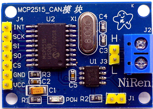
 Design with MCP2515 in Cirkit Designer
Introduction
The MCP2515, manufactured by Malith (Part ID: 123), is a standalone CAN (Controller Area Network) controller that enables communication between devices using the SPI (Serial Peripheral Interface). It is widely used in automotive and industrial applications where reliable and robust communication is essential. The MCP2515 is designed to interface with microcontrollers, making it a versatile solution for implementing CAN communication in embedded systems.
Explore Projects Built with MCP2515
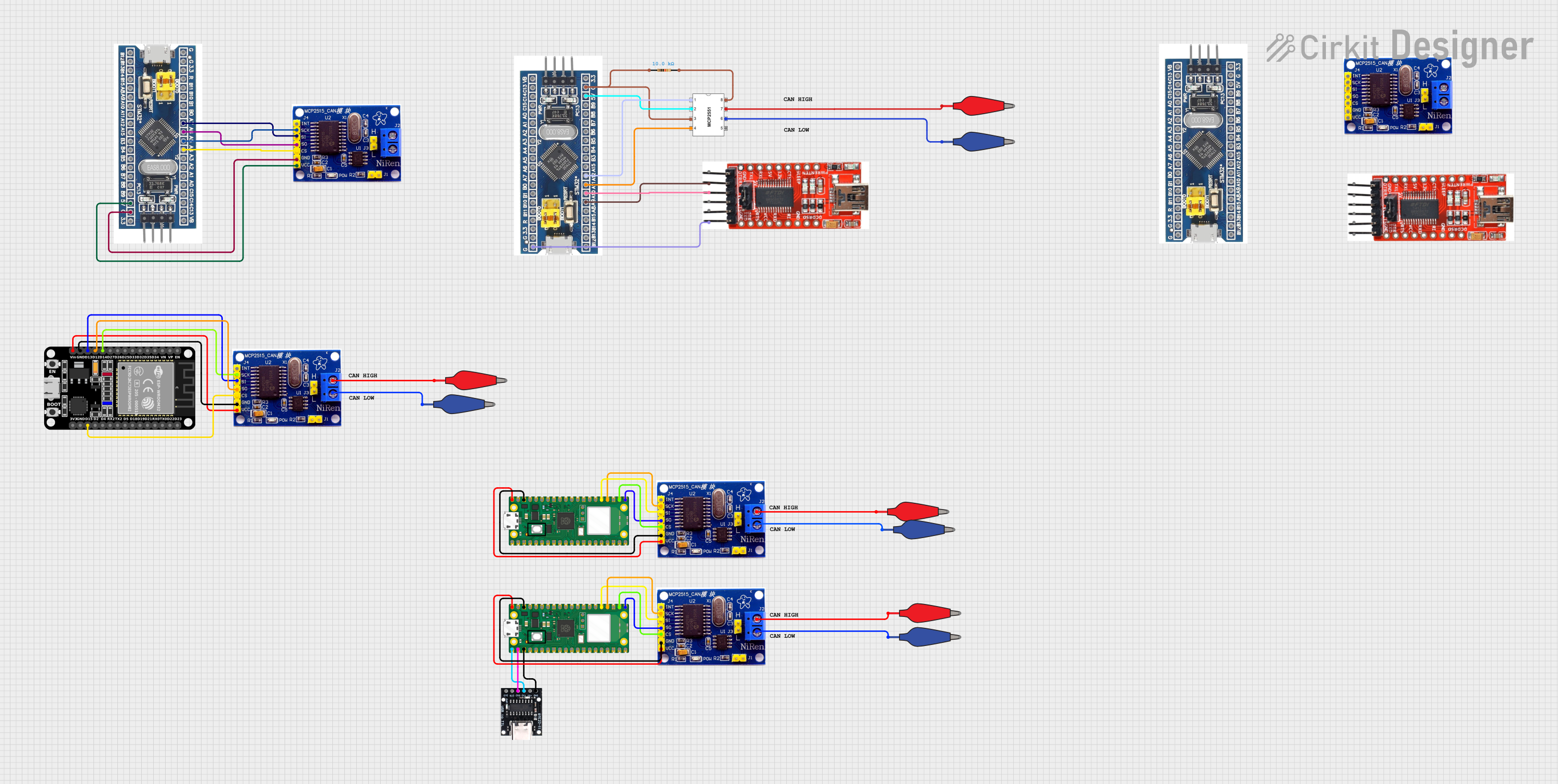 Open Project in Cirkit Designer
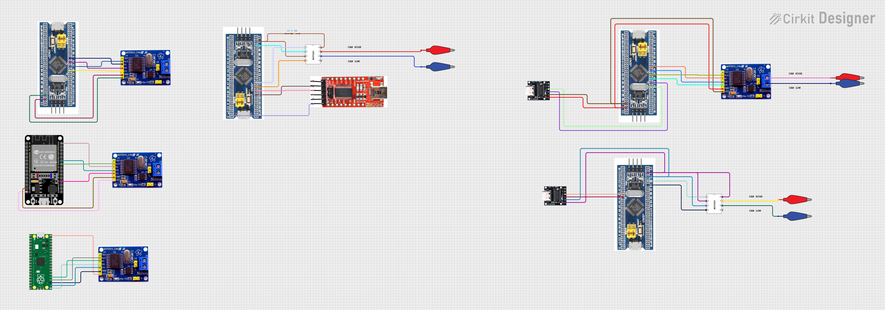 Open Project in Cirkit Designer
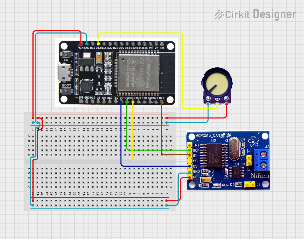 Open Project in Cirkit Designer
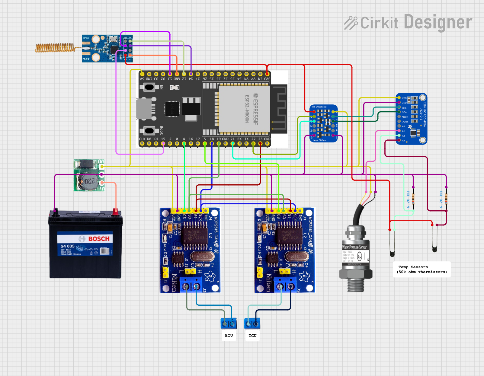 Open Project in Cirkit Designer
Explore Projects Built with MCP2515
Open Project in Cirkit DesignerOpen Project in Cirkit DesignerOpen Project in Cirkit DesignerOpen Project in Cirkit DesignerCommon Applications and Use Cases
- Automotive systems for in-vehicle communication
- Industrial automation and control systems
- Robotics and IoT devices requiring CAN communication
- Diagnostic tools for CAN-based networks
- Data logging and monitoring systems
Technical Specifications
The MCP2515 is a high-performance CAN controller with the following key specifications:
| Parameter | Value |
|---|---|
| Operating Voltage | 2.7V to 5.5V |
| Communication Interface | SPI (up to 10 MHz) |
| CAN Protocol Support | CAN 2.0A and CAN 2.0B |
| Maximum CAN Baud Rate | 1 Mbps |
| Operating Temperature Range | -40°C to +125°C |
| Package Options | SOIC, PDIP, TSSOP |
Pin Configuration and Descriptions
The MCP2515 has an 18-pin configuration. Below is the pinout and description:
| Pin Number | Pin Name | Description |
|---|---|---|
| 1 | VSS | Ground connection |
| 2 | VDD | Positive supply voltage |
| 3 | CS | Chip Select (active low) for SPI communication |
| 4 | SCK | SPI Clock input |
| 5 | SI | SPI Data input |
| 6 | SO | SPI Data output |
| 7 | INT | Interrupt output (active low) |
| 8 | RX0BF | Receive Buffer 0 Full interrupt output |
| 9 | RX1BF | Receive Buffer 1 Full interrupt output |
| 10 | RESET | Resets the MCP2515 (active low) |
| 11 | TXCAN | CAN Transmit output |
| 12 | RXCAN | CAN Receive input |
| 13-18 | OSC1, OSC2 | Oscillator pins for external clock source |
Usage Instructions
How to Use the MCP2515 in a Circuit
- Power Supply: Connect the VDD pin to a 3.3V or 5V power source and the VSS pin to ground.
- SPI Communication: Connect the SPI pins (CS, SCK, SI, SO) to the corresponding SPI pins on your microcontroller.
- CAN Bus Connection: Connect the TXCAN and RXCAN pins to a CAN transceiver (e.g., MCP2551) for interfacing with the CAN bus.
- Oscillator: Attach an external crystal oscillator (typically 8 MHz or 16 MHz) to the OSC1 and OSC2 pins.
- Interrupts: Use the INT pin to handle interrupts for efficient communication.
Important Considerations and Best Practices
- Ensure proper termination resistors (typically 120 ohms) are placed at both ends of the CAN bus.
- Use decoupling capacitors (e.g., 0.1 µF) near the VDD pin to stabilize the power supply.
- Configure the MCP2515 registers correctly for your desired CAN baud rate and operating mode.
- Use a CAN transceiver to interface the MCP2515 with the physical CAN bus.
Example Code for Arduino UNO
Below is an example of how to use the MCP2515 with an Arduino UNO to send a CAN message:
#include <SPI.h>
#include <mcp2515.h> // Include the MCP2515 library

struct can_frame canMsg; // Define a CAN frame structure
MCP2515 mcp2515(10);     // Initialize MCP2515 with CS pin connected to pin 10

void setup() {
  Serial.begin(9600); // Start serial communication for debugging
  SPI.begin();        // Initialize SPI communication

  // Initialize MCP2515 and set it to normal mode
  if (mcp2515.reset() != MCP2515::ERROR_OK) {
    Serial.println("MCP2515 reset failed!");
    while (1);
  }
  mcp2515.setNormalMode();

  Serial.println("MCP2515 Initialized!");

  // Prepare a CAN message
  canMsg.can_id = 0x123; // Set CAN ID
  canMsg.can_dlc = 2;    // Set data length (2 bytes)
  canMsg.data[0] = 0xAB; // First byte of data
  canMsg.data[1] = 0xCD; // Second byte of data
}

void loop() {
  // Send the CAN message
  if (mcp2515.sendMessage(&canMsg) == MCP2515::ERROR_OK) {
    Serial.println("Message sent successfully!");
  } else {
    Serial.println("Error sending message!");
  }
  delay(1000); // Wait 1 second before sending the next message
}
Troubleshooting and FAQs
Common Issues and Solutions
MCP2515 Not Responding to SPI Commands
- Ensure the CS pin is correctly connected and configured in your code.
- Verify that the SPI clock speed does not exceed 10 MHz.
CAN Messages Not Being Sent or Received
- Check the CAN bus wiring and ensure proper termination resistors are in place.
- Verify that the CAN transceiver is functioning correctly and is compatible with the MCP2515.
Interrupts Not Triggering
- Ensure the INT pin is connected to the correct interrupt pin on your microcontroller.
- Verify that interrupts are enabled in the MCP2515 configuration.
FAQs
Q: Can the MCP2515 operate without an external oscillator?
A: No, the MCP2515 requires an external crystal oscillator (e.g., 8 MHz or 16 MHz) for proper operation.
Q: What is the maximum CAN bus length supported by the MCP2515?
A: The maximum bus length depends on the CAN baud rate. For example, at 1 Mbps, the maximum length is approximately 40 meters.
Q: Can the MCP2515 be used with 3.3V microcontrollers?
A: Yes, the MCP2515 supports operating voltages from 2.7V to 5.5V, making it compatible with 3.3V systems.