How to Use LCU30H gate controller: Examples, Pinouts, and Specs
Introduction
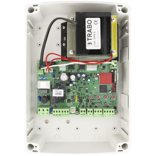
The LCU30H Gate Controller, manufactured by Ditec, is a versatile and reliable device designed to manage and control the operation of automated gate systems. It is commonly used in industrial, commercial, and residential environments where precise and automated gate control is required. The controller integrates inputs for sensors and outputs for actuators, enabling smooth and efficient gate movements based on user-defined conditions.
Explore Projects Built with LCU30H gate controller


Explore Projects Built with LCU30H gate controller
Common Applications and Use Cases
- Automated sliding or swing gates in residential and commercial properties.
- Industrial gate systems requiring precise control and safety features.
- Integration with access control systems, such as RFID readers or keypads.
- Smart home or building automation systems for enhanced security and convenience.
Technical Specifications
Key Technical Details
| Parameter | Specification |
|---|---|
| Manufacturer | Ditec |
| Part ID | LCU30H |
| Input Voltage | 230V AC ±10% |
| Output Voltage | 24V DC (for actuators and accessories) |
| Maximum Motor Power | 300W |
| Operating Temperature | -20°C to +55°C |
| Protection Rating | IP54 |
| Communication Interface | Wired (optional wireless modules) |
| Safety Features | Obstacle detection, emergency stop |
Pin Configuration and Descriptions
The LCU30H features a terminal block for connecting various inputs and outputs. Below is the pin configuration:
Terminal Block Pinout
| Pin Number | Label | Description |
|---|---|---|
| 1 | L | Live input (230V AC) |
| 2 | N | Neutral input (230V AC) |
| 3 | PE | Protective Earth |
| 4 | MOTOR+ | Motor positive terminal |
| 5 | MOTOR- | Motor negative terminal |
| 6 | SENSOR1 | Input for safety sensor 1 (e.g., photocell) |
| 7 | SENSOR2 | Input for safety sensor 2 |
| 8 | OPEN_CMD | Command input for opening the gate |
| 9 | CLOSE_CMD | Command input for closing the gate |
| 10 | STOP_CMD | Emergency stop input |
| 11 | 24V_OUT | 24V DC output for accessories |
| 12 | GND | Ground for accessories |
Usage Instructions
How to Use the LCU30H in a Circuit
- Power Connection: Connect the live (L), neutral (N), and protective earth (PE) terminals to a 230V AC power source.
- Motor Connection: Connect the motor's positive and negative terminals to the MOTOR+ and MOTOR- pins, respectively.
- Sensor Integration: Attach safety sensors (e.g., photocells) to SENSOR1 and SENSOR2 inputs. Ensure proper alignment and functionality of the sensors.
- Command Inputs: Wire external control devices (e.g., push buttons, keypads) to the OPEN_CMD, CLOSE_CMD, and STOP_CMD terminals.
- Accessory Power: Use the 24V_OUT and GND terminals to power additional accessories, such as indicator lights or wireless modules.
Important Considerations and Best Practices
- Safety First: Always disconnect the power supply before performing any wiring or maintenance.
- Sensor Placement: Install safety sensors at appropriate positions to detect obstacles effectively and prevent accidents.
- Cable Management: Use shielded cables for sensor and command inputs to minimize interference.
- Testing: After installation, test the system thoroughly to ensure all inputs and outputs function as expected.
- Firmware Updates: Check for firmware updates from Ditec to ensure optimal performance and compatibility.
Example: Connecting to an Arduino UNO
The LCU30H can be integrated with an Arduino UNO for advanced automation. Below is an example code snippet to control the gate using digital pins:
// Define Arduino pins connected to the LCU30H command inputs
const int openCmdPin = 2;  // Pin connected to OPEN_CMD terminal
const int closeCmdPin = 3; // Pin connected to CLOSE_CMD terminal
const int stopCmdPin = 4;  // Pin connected to STOP_CMD terminal

void setup() {
  // Set pins as outputs
  pinMode(openCmdPin, OUTPUT);
  pinMode(closeCmdPin, OUTPUT);
  pinMode(stopCmdPin, OUTPUT);

  // Initialize all commands to LOW (inactive)
  digitalWrite(openCmdPin, LOW);
  digitalWrite(closeCmdPin, LOW);
  digitalWrite(stopCmdPin, LOW);
}

void loop() {
  // Example: Open the gate for 5 seconds, then stop
  digitalWrite(openCmdPin, HIGH); // Send open command
  delay(5000);                    // Wait for 5 seconds
  digitalWrite(openCmdPin, LOW);  // Stop the open command

  // Example: Close the gate for 5 seconds, then stop
  digitalWrite(closeCmdPin, HIGH); // Send close command
  delay(5000);                     // Wait for 5 seconds
  digitalWrite(closeCmdPin, LOW);  // Stop the close command

  // Example: Emergency stop
  digitalWrite(stopCmdPin, HIGH);  // Activate emergency stop
  delay(1000);                     // Hold stop for 1 second
  digitalWrite(stopCmdPin, LOW);   // Deactivate emergency stop
}
Troubleshooting and FAQs
Common Issues and Solutions
| Issue | Possible Cause | Solution |
|---|---|---|
| Gate does not move | Power supply issue | Check the 230V AC input and connections. |
| Gate stops unexpectedly | Obstacle detected by sensors | Ensure sensors are aligned and unobstructed. |
| Motor runs but gate does not move | Mechanical issue with the gate | Inspect the gate mechanism for obstructions or damage. |
| Accessories not powered | Faulty 24V DC output | Verify the 24V_OUT terminal and connected accessories. |
| Commands not responding | Loose or incorrect wiring | Check the wiring of command inputs. |
FAQs
Can the LCU30H be used with solar power systems?
- Yes, as long as the solar system provides a stable 230V AC output or a compatible inverter is used.
What is the maximum gate weight supported?
- The LCU30H supports motors up to 300W, which typically corresponds to gates weighing up to 500kg. Check motor specifications for exact compatibility.
Can I integrate the LCU30H with a smart home system?
- Yes, the LCU30H can be integrated with smart home systems using additional modules or relays.
How do I reset the controller?
- Refer to the user manual provided by Ditec for detailed reset instructions, as it may vary by firmware version.
By following this documentation, users can effectively install, operate, and troubleshoot the LCU30H gate controller for a wide range of applications.