How to Use 120x120x32 24V Blower Fan: Examples, Pinouts, and Specs
Introduction
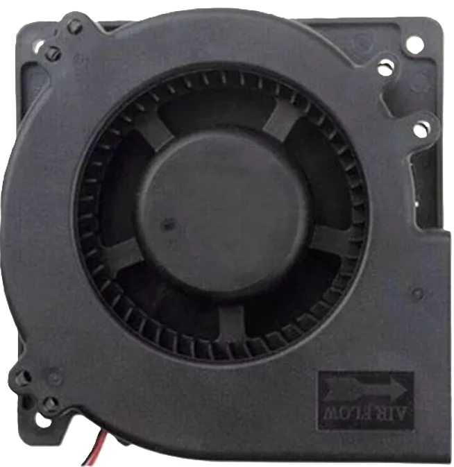
The 120x120x32 24V Blower Fan is a high-performance cooling solution designed to provide directed airflow for electronic components and systems. With its compact dimensions of 120x120x32 mm, this blower fan is ideal for applications requiring efficient heat dissipation in confined spaces. It operates at a voltage of 24V, making it suitable for a wide range of industrial and consumer electronics.
Explore Projects Built with 120x120x32 24V Blower Fan


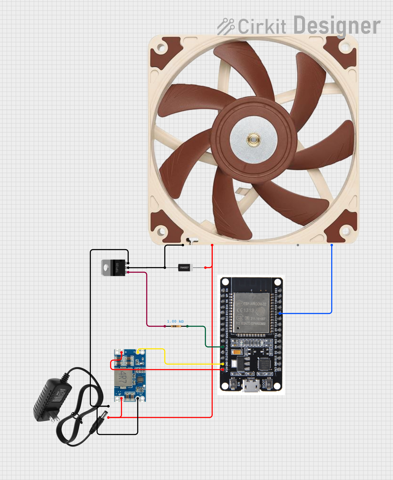
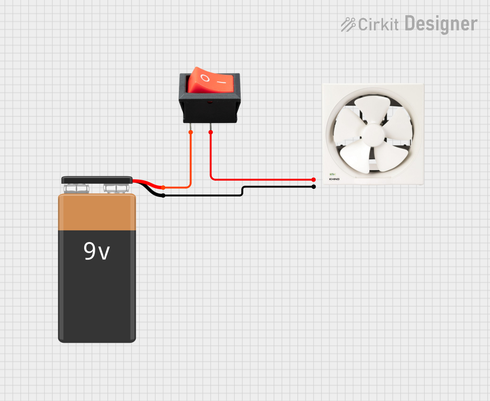
Explore Projects Built with 120x120x32 24V Blower Fan
Common Applications and Use Cases
- Cooling for electronic enclosures and cabinets
- Heat dissipation for power supplies and amplifiers
- Ventilation for 3D printers and other machinery
- Airflow management in HVAC systems
- Cooling for computer servers and networking equipment
Technical Specifications
Key Technical Details
| Parameter | Value |
|---|---|
| Dimensions | 120x120x32 mm |
| Operating Voltage | 24V DC |
| Current Rating | 0.5A |
| Power Consumption | 12W |
| Airflow | 85 CFM (Cubic Feet per Minute) |
| Noise Level | 35 dBA |
| Bearing Type | Ball Bearing |
| Connector Type | 2-pin Molex |
Pin Configuration and Descriptions
| Pin Number | Pin Name | Description |
|---|---|---|
| 1 | VCC | Positive supply voltage (24V DC) |
| 2 | GND | Ground (0V) |
Usage Instructions
How to Use the Component in a Circuit
- Power Supply: Ensure you have a stable 24V DC power supply capable of providing at least 0.5A of current.
- Connections:
- Connect the VCC pin of the blower fan to the positive terminal of the 24V power supply.
- Connect the GND pin of the blower fan to the ground terminal of the power supply.
- Mounting: Secure the blower fan in the desired location using screws or mounting brackets. Ensure that the airflow direction aligns with your cooling requirements.
Important Considerations and Best Practices
- Voltage Compatibility: Verify that the power supply voltage matches the blower fan's operating voltage (24V DC).
- Current Rating: Ensure the power supply can provide sufficient current (0.5A) to avoid overheating or damage.
- Airflow Direction: Install the blower fan in a way that optimizes airflow over the components that need cooling.
- Noise Level: Consider the noise level (35 dBA) in noise-sensitive environments.
- Maintenance: Periodically clean the fan blades and housing to prevent dust buildup and maintain optimal performance.
Troubleshooting and FAQs
Common Issues and Solutions
Fan Not Spinning:
- Check Power Supply: Ensure the power supply is providing 24V DC and is properly connected.
- Inspect Connections: Verify that the VCC and GND connections are secure and correctly oriented.
- Measure Voltage: Use a multimeter to check the voltage at the fan's terminals.
Excessive Noise:
- Clean the Fan: Dust and debris can cause noise. Clean the fan blades and housing.
- Check Mounting: Ensure the fan is securely mounted to prevent vibrations.
Insufficient Airflow:
- Verify Voltage: Ensure the fan is receiving the correct voltage (24V DC).
- Check for Obstructions: Make sure there are no obstructions blocking the airflow.
FAQs
Q: Can I use a 12V power supply with this blower fan? A: No, the blower fan is designed to operate at 24V DC. Using a lower voltage will result in insufficient performance and may damage the fan.
Q: How do I control the speed of the blower fan? A: This blower fan does not have built-in speed control. You can use an external PWM (Pulse Width Modulation) controller to adjust the speed.
Q: Is the blower fan waterproof? A: No, this blower fan is not waterproof. It should be used in dry environments to prevent damage.
Example Code for Arduino UNO
If you want to control the blower fan using an Arduino UNO and a MOSFET for speed control, you can use the following example code:
// Define the pin connected to the gate of the MOSFET
const int fanPin = 9;

void setup() {
  // Set the fan pin as an output
  pinMode(fanPin, OUTPUT);
}

void loop() {
  // Set the fan speed to 50% using PWM
  analogWrite(fanPin, 128); // 128 is 50% of 255

  // Run the fan at 50% speed for 10 seconds
  delay(10000);

  // Turn off the fan
  analogWrite(fanPin, 0);

  // Wait for 5 seconds before turning the fan on again
  delay(5000);
}
In this example, a MOSFET is used to control the blower fan's speed via PWM. The fan is set to run at 50% speed for 10 seconds, then turned off for 5 seconds in a loop.
By following this documentation, you should be able to effectively integrate and utilize the 120x120x32 24V Blower Fan in your projects.