How to Use XL4005 DC-DC 5A ADJUSTABLE STEPDOWN POWER SUPPLY MODULE: Examples, Pinouts, and Specs
Introduction
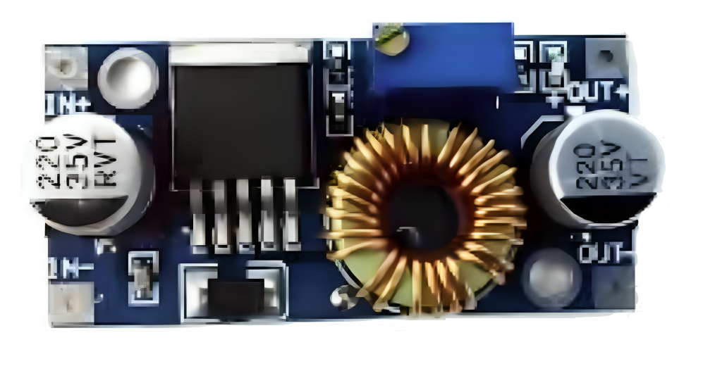
The XL4005 DC-DC Adjustable Stepdown Power Supply Module is a high-performance buck converter designed to step down DC voltage efficiently. Manufactured by Phipps Electronics (Part ID: PHI1002207), this module is capable of delivering up to 5A of output current with an adjustable output voltage. It is widely used in applications requiring stable and efficient power delivery, such as powering microcontrollers, LED strips, battery chargers, and other electronic devices.
Explore Projects Built with XL4005 DC-DC 5A ADJUSTABLE STEPDOWN POWER SUPPLY MODULE


Explore Projects Built with XL4005 DC-DC 5A ADJUSTABLE STEPDOWN POWER SUPPLY MODULE
Common Applications
- Powering Arduino, Raspberry Pi, and other microcontroller boards
- LED lighting systems
- Battery charging circuits
- DIY electronics projects
- Voltage regulation in industrial and automotive systems
Technical Specifications
Below are the key technical details of the XL4005 module:
| Parameter | Value |
|---|---|
| Input Voltage Range | 5V to 32V DC |
| Output Voltage Range | 0.8V to 30V DC (adjustable) |
| Maximum Output Current | 5A (with proper heat dissipation) |
| Output Power | Up to 75W |
| Efficiency | Up to 96% (depending on input/output voltage) |
| Switching Frequency | 300 kHz |
| Operating Temperature | -40°C to +85°C |
| Dimensions | 51mm x 26mm x 14mm |
Pin Configuration and Descriptions
The XL4005 module has the following pinout:
| Pin Name | Description |
|---|---|
| VIN | Input voltage (5V to 32V DC) |
| GND | Ground connection |
| VOUT | Output voltage (0.8V to 30V DC, adjustable via potentiometer) |
Usage Instructions
How to Use the XL4005 in a Circuit
- Connect Input Voltage:
- Connect the positive terminal of your DC power source to the VIN pin.
- Connect the negative terminal of your DC power source to the GND pin.
- Connect Load:
- Connect the positive terminal of your load to the VOUT pin.
- Connect the negative terminal of your load to the GND pin.
- Adjust Output Voltage:
- Use the onboard potentiometer to adjust the output voltage. Turn clockwise to increase the voltage and counterclockwise to decrease it.
- Verify Output:
- Use a multimeter to measure the output voltage and ensure it matches your desired value before connecting sensitive devices.
Important Considerations and Best Practices
- Heat Dissipation: The module can handle up to 5A of current, but proper heat dissipation (e.g., a heatsink or active cooling) is required for high-power applications.
- Input Voltage: Ensure the input voltage is at least 1.5V higher than the desired output voltage for proper operation.
- Polarity: Double-check the polarity of your connections to avoid damaging the module.
- Load Testing: Test the module with a dummy load before connecting sensitive devices to ensure stable operation.
Example: Using XL4005 with Arduino UNO
The XL4005 can be used to power an Arduino UNO by stepping down a 12V DC input to 5V. Below is an example circuit and Arduino code to blink an LED:
Circuit Connections
- Connect a 12V DC power source to the VIN and GND pins of the XL4005.
- Adjust the output voltage to 5V using the potentiometer.
- Connect the VOUT pin to the Arduino's 5V pin and the GND pin to the Arduino's GND pin.
- Connect an LED to pin 13 of the Arduino with a 220-ohm resistor in series.
Arduino Code
// Simple LED Blink Example
// This code blinks an LED connected to pin 13 of the Arduino UNO.

void setup() {
  pinMode(13, OUTPUT); // Set pin 13 as an output
}

void loop() {
  digitalWrite(13, HIGH); // Turn the LED on
  delay(1000);            // Wait for 1 second
  digitalWrite(13, LOW);  // Turn the LED off
  delay(1000);            // Wait for 1 second
}
Troubleshooting and FAQs
Common Issues and Solutions
No Output Voltage:
- Ensure the input voltage is within the specified range (5V to 32V DC).
- Check all connections for proper polarity and secure contact.
- Verify that the potentiometer is not set to the minimum output voltage.
Overheating:
- Ensure the module is not exceeding its maximum current rating of 5A.
- Add a heatsink or active cooling if the module is used in high-power applications.
Output Voltage Fluctuations:
- Check the input voltage for stability.
- Ensure the load is within the module's power capacity.
- Verify that the potentiometer is not loose or damaged.
Module Not Powering On:
- Double-check the polarity of the input voltage.
- Inspect the module for physical damage or burnt components.
FAQs
Q: Can the XL4005 be used to charge batteries?
A: Yes, the XL4005 can be used to charge batteries, but you must ensure the output voltage and current are set according to the battery's specifications.
Q: What is the maximum input voltage for the XL4005?
A: The maximum input voltage is 32V DC. Exceeding this value may damage the module.
Q: Can I use the XL4005 to power a Raspberry Pi?
A: Yes, the XL4005 can step down voltage to 5V to power a Raspberry Pi. Ensure the output is stable and sufficient current (at least 2.5A) is available.
Q: How do I know if the module is overheating?
A: If the module becomes too hot to touch or shuts down intermittently, it is likely overheating. Add a heatsink or reduce the load to prevent damage.
By following this documentation, you can effectively use the XL4005 DC-DC Adjustable Stepdown Power Supply Module in your projects.