Cirkit Designer Logo
Cirkit Designer
Your all-in-one circuit design IDE
Home / 
Component Documentation

How to Use L9110: Examples, Pinouts, and Specs

Image of L9110
Cirkit Designer LogoDesign with L9110 in Cirkit Designer

Introduction

The L9110 is an integrated circuit designed to control the direction and speed of DC motors. It consists of two H-bridge drivers that can independently control two small to medium-sized DC motors. The L9110 is widely used in robotics, automation projects, and various DIY applications due to its simplicity and efficiency.

Explore Projects Built with L9110

Use Cirkit Designer to design, explore, and prototype these projects online. Some projects support real-time simulation. Click "Open Project" to start designing instantly!
Cellular-Enabled IoT Device with Real-Time Clock and Power Management
Image of LRCM PHASE 2 BASIC: A project utilizing L9110 in a practical application
This circuit features a LilyGo-SIM7000G module for cellular communication and GPS functionality, interfaced with an RTC DS3231 for real-time clock capabilities. It includes voltage sensing through two voltage sensor modules, and uses an 8-channel opto-coupler for isolating different parts of the circuit. Power management is handled by a buck converter connected to a DC power source and batteries, with a fuse for protection and a rocker switch for on/off control. Additionally, there's an LED for indication purposes.
Cirkit Designer LogoOpen Project in Cirkit Designer
Arduino Leonardo Soldier Tracking System with GPS, GSM, and Environmental Sensors
Image of project: A project utilizing L9110 in a practical application
This circuit is designed for a soldier tracking system that monitors environmental conditions and location. It uses an Arduino Leonardo to interface with a GPS module for location tracking, a SIM900A GSM module for SMS communication, a temperature sensor (LM35) for ambient temperature measurement, and an LDR photoresistor for light intensity which could be used as a proxy for heartbeat monitoring. The system can send the soldier's location, temperature, and heartbeat data via SMS and displays status information on an LCD screen connected via an I2C module.
Cirkit Designer LogoOpen Project in Cirkit Designer
Battery-Powered Emergency Alert System with NUCLEO-F072RB, SIM800L, and GPS NEO 6M
Image of women safety: A project utilizing L9110 in a practical application
This circuit is an emergency alert system that uses a NUCLEO-F072RB microcontroller to send SMS alerts and make calls via a SIM800L GSM module, while obtaining location data from a GPS NEO 6M module. The system is powered by a Li-ion battery and includes a TP4056 module for battery charging and protection, with a rocker switch to control power to the microcontroller.
Cirkit Designer LogoOpen Project in Cirkit Designer
Arduino UNO-Based Battery-Powered Robotic Car with Ultrasonic and IR Sensors
Image of micon: A project utilizing L9110 in a practical application
This circuit is a robotic system controlled by an Arduino UNO, featuring motor drivers (L9110) to control multiple hobby motors, an ultrasonic sensor (HC-SR04) for distance measurement, IR sensors for obstacle detection, and a Bluetooth module (HC-06) for wireless communication. The system is powered by a 2x 18650 battery pack and includes a rocker switch for power control.
Cirkit Designer LogoOpen Project in Cirkit Designer

Explore Projects Built with L9110

Use Cirkit Designer to design, explore, and prototype these projects online. Some projects support real-time simulation. Click "Open Project" to start designing instantly!
Image of LRCM PHASE 2 BASIC: A project utilizing L9110 in a practical application
Cellular-Enabled IoT Device with Real-Time Clock and Power Management
This circuit features a LilyGo-SIM7000G module for cellular communication and GPS functionality, interfaced with an RTC DS3231 for real-time clock capabilities. It includes voltage sensing through two voltage sensor modules, and uses an 8-channel opto-coupler for isolating different parts of the circuit. Power management is handled by a buck converter connected to a DC power source and batteries, with a fuse for protection and a rocker switch for on/off control. Additionally, there's an LED for indication purposes.
Cirkit Designer LogoOpen Project in Cirkit Designer
Image of project: A project utilizing L9110 in a practical application
Arduino Leonardo Soldier Tracking System with GPS, GSM, and Environmental Sensors
This circuit is designed for a soldier tracking system that monitors environmental conditions and location. It uses an Arduino Leonardo to interface with a GPS module for location tracking, a SIM900A GSM module for SMS communication, a temperature sensor (LM35) for ambient temperature measurement, and an LDR photoresistor for light intensity which could be used as a proxy for heartbeat monitoring. The system can send the soldier's location, temperature, and heartbeat data via SMS and displays status information on an LCD screen connected via an I2C module.
Cirkit Designer LogoOpen Project in Cirkit Designer
Image of women safety: A project utilizing L9110 in a practical application
Battery-Powered Emergency Alert System with NUCLEO-F072RB, SIM800L, and GPS NEO 6M
This circuit is an emergency alert system that uses a NUCLEO-F072RB microcontroller to send SMS alerts and make calls via a SIM800L GSM module, while obtaining location data from a GPS NEO 6M module. The system is powered by a Li-ion battery and includes a TP4056 module for battery charging and protection, with a rocker switch to control power to the microcontroller.
Cirkit Designer LogoOpen Project in Cirkit Designer
Image of micon: A project utilizing L9110 in a practical application
Arduino UNO-Based Battery-Powered Robotic Car with Ultrasonic and IR Sensors
This circuit is a robotic system controlled by an Arduino UNO, featuring motor drivers (L9110) to control multiple hobby motors, an ultrasonic sensor (HC-SR04) for distance measurement, IR sensors for obstacle detection, and a Bluetooth module (HC-06) for wireless communication. The system is powered by a 2x 18650 battery pack and includes a rocker switch for power control.
Cirkit Designer LogoOpen Project in Cirkit Designer

Common Applications and Use Cases

  • Robotics: Driving wheels or tracks.
  • Automation: Controlling actuators and mechanical systems.
  • Hobby Projects: RC cars, drones, and other motorized gadgets.

Technical Specifications

Key Technical Details

  • Operating Voltage: 2.5V to 12V
  • Output Current: Up to 800mA per channel
  • Peak Output Current: 1.5A (for a short duration)
  • Standby Control to Save Power
  • Input Logic Voltage: 2.5V to 12V

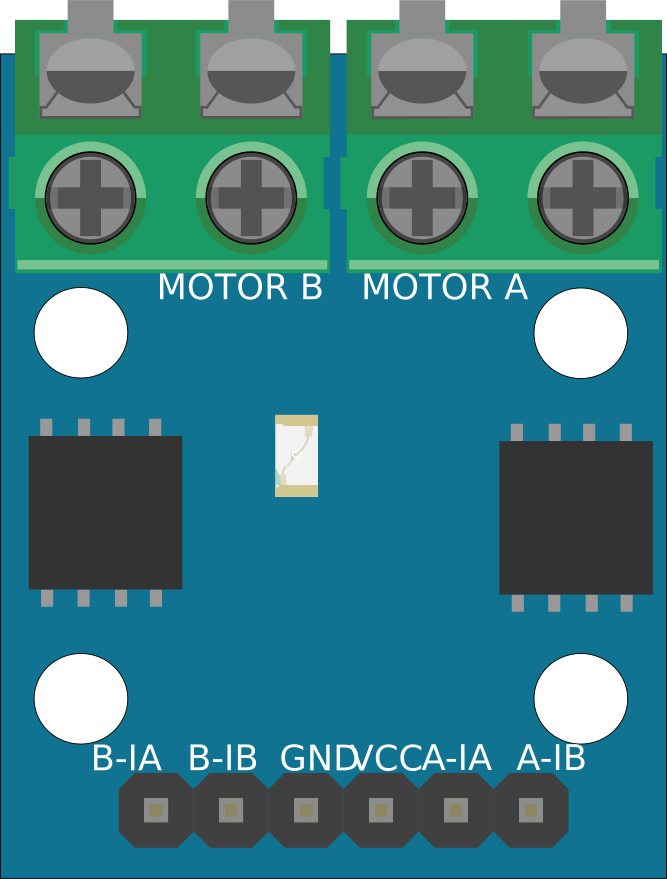
Pin Configuration and Descriptions

Pin Number Pin Name Description
1 Vcc Motor power supply (2.5V to 12V)
2 GND Ground
3 B-IA Input A for motor B, logic level
4 B-IB Input B for motor B, logic level
5 A-IA Input A for motor A, logic level
6 A-IB Input B for motor A, logic level
7 A-O1 Output 1 for motor A
8 A-O2 Output 2 for motor A
9 B-O1 Output 1 for motor B
10 B-O2 Output 2 for motor B

Usage Instructions

How to Use the Component in a Circuit

  1. Connect the motor power supply to the Vcc and GND pins.
  2. Connect the motors to the output pins A-O1/A-O2 and B-O1/B-O2.
  3. Apply logic signals to the input pins A-IA/A-IB and B-IA/B-IB to control the motors.

Important Considerations and Best Practices

  • Ensure the power supply voltage and motor current do not exceed the IC's ratings.
  • Use a proper heat sink if operating near the maximum current rating.
  • Avoid shorting the output pins as it may damage the IC.
  • Use flyback diodes across the motors to protect the IC from voltage spikes.

Example Code for Arduino UNO

// Define the L9110 control pins connected to the Arduino
const int motorA_IA = 2;
const int motorA_IB = 3;
const int motorB_IA = 4;
const int motorB_IB = 5;

void setup() {
  // Set the motor control pins as outputs
  pinMode(motorA_IA, OUTPUT);
  pinMode(motorA_IB, OUTPUT);
  pinMode(motorB_IA, OUTPUT);
  pinMode(motorB_IB, OUTPUT);
}

void loop() {
  // Rotate Motor A clockwise
  digitalWrite(motorA_IA, HIGH);
  digitalWrite(motorA_IB, LOW);
  delay(1000); // Run for 1 second

  // Rotate Motor A counterclockwise
  digitalWrite(motorA_IA, LOW);
  digitalWrite(motorA_IB, HIGH);
  delay(1000); // Run for 1 second

  // Stop Motor A
  digitalWrite(motorA_IA, LOW);
  digitalWrite(motorA_IB, LOW);
  delay(1000); // Stop for 1 second

  // The same logic can be applied to control Motor B using motorB_IA and motorB_IB
}

Troubleshooting and FAQs

Common Issues Users Might Face

  • Motor not running: Check power supply and connections.
  • Overheating: Ensure current is within limits and use a heat sink.
  • Inconsistent motor speed: Verify the input logic levels and power supply stability.

Solutions and Tips for Troubleshooting

  • Double-check wiring against the pin configuration.
  • Measure the voltage at the motor terminals to ensure proper operation.
  • Use a multimeter to check for shorts or open circuits in the connections.

FAQs

Q: Can the L9110 drive stepper motors? A: No, the L9110 is designed for DC motors and does not have the necessary control for stepper motors.

Q: What is the maximum frequency for PWM control? A: The L9110 can typically handle PWM frequencies up to 100kHz, but for most applications, a frequency of around 1kHz to 25kHz is sufficient.

Q: Can I use the L9110 without a microcontroller? A: Yes, you can use manual switches or logic gates to control the inputs, but a microcontroller like an Arduino provides more flexibility and control options.