How to Use ST7789 TFT: Examples, Pinouts, and Specs
Introduction
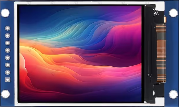
The ST7789 TFT is a compact, full-color display driver designed for TFT LCD screens. It is widely used in embedded systems and portable devices due to its small size, vibrant color reproduction, and efficient communication interface. The ST7789 supports a resolution of 240x240 pixels, making it ideal for applications requiring high-quality visuals in a compact form factor. Its SPI (Serial Peripheral Interface) communication ensures compatibility with a wide range of microcontrollers, including popular development boards like the Arduino UNO.
Explore Projects Built with ST7789 TFT


Explore Projects Built with ST7789 TFT
Common Applications and Use Cases
- Smartwatches and wearable devices
- Portable gaming consoles
- IoT dashboards and displays
- Industrial control panels
- Educational and hobbyist projects
Technical Specifications
Below are the key technical details of the ST7789 TFT:
| Parameter | Value |
|---|---|
| Resolution | 240x240 pixels |
| Interface | SPI (4-wire or 3-wire) |
| Operating Voltage | 2.8V to 3.3V |
| Logic Level | 3.3V (5V-tolerant with level shifter) |
| Display Colors | 65K (16-bit color) |
| Backlight Voltage | 3.0V to 3.3V |
| Backlight Current | ~20mA |
| Operating Temperature | -30°C to 85°C |
| Dimensions | Varies by module (e.g., 1.3", 1.54") |
Pin Configuration and Descriptions
The ST7789 TFT module typically has the following pin configuration:
| Pin Name | Description |
|---|---|
| VCC | Power supply input (2.8V to 3.3V) |
| GND | Ground connection |
| SCL (CLK) | SPI clock signal |
| SDA (MOSI) | SPI data input (Master Out Slave In) |
| RES (RST) | Reset pin (active low) |
| DC (A0) | Data/Command control pin (High = Data, Low = Command) |
| CS | Chip Select (active low) |
| BLK (LED) | Backlight control (connect to 3.3V or PWM pin) |
Note: Some modules may have additional or fewer pins depending on the manufacturer. Always refer to the specific module's datasheet for exact details.
Usage Instructions
How to Use the ST7789 TFT in a Circuit
- Power Supply: Connect the VCC pin to a 3.3V power source and GND to ground. If using a 5V microcontroller, use a level shifter to avoid damaging the display.
- SPI Communication: Connect the SCL, SDA, and CS pins to the corresponding SPI pins on your microcontroller. Ensure proper wiring to avoid communication errors.
- Control Pins: Connect the RES and DC pins to GPIO pins on your microcontroller. These are used for resetting the display and toggling between data and command modes.
- Backlight: Connect the BLK pin to 3.3V for constant backlight or to a PWM pin for adjustable brightness.
Important Considerations and Best Practices
- Voltage Levels: Ensure all logic signals are at 3.3V. Use level shifters if your microcontroller operates at 5V.
- Capacitors: Add decoupling capacitors (e.g., 0.1µF) near the VCC and GND pins to stabilize the power supply.
- Initialization: Properly initialize the display using the correct sequence of commands as specified in the ST7789 datasheet.
- Library Support: Use libraries like Adafruit_GFX and Adafruit_ST7789 for easier integration with Arduino and other platforms.
Example Code for Arduino UNO
Below is an example of how to use the ST7789 TFT with an Arduino UNO:
#include <Adafruit_GFX.h>       // Core graphics library
#include <Adafruit_ST7789.h>    // ST7789 driver library
#include <SPI.h>                // SPI library

// Define pins for the ST7789
#define TFT_CS    10  // Chip Select pin
#define TFT_RST   9   // Reset pin
#define TFT_DC    8   // Data/Command pin

// Create an instance of the ST7789 display
Adafruit_ST7789 tft = Adafruit_ST7789(TFT_CS, TFT_DC, TFT_RST);

void setup() {
  // Initialize the serial monitor
  Serial.begin(9600);
  Serial.println("ST7789 TFT Test");

  // Initialize the display
  tft.init(240, 240);  // Initialize with 240x240 resolution
  tft.setRotation(1);  // Set display orientation (0-3)

  // Fill the screen with a color
  tft.fillScreen(ST77XX_BLACK);

  // Draw some text
  tft.setTextColor(ST77XX_WHITE);
  tft.setTextSize(2);
  tft.setCursor(10, 10);
  tft.println("Hello, ST7789!");
}

void loop() {
  // Add your code here to update the display
}
Note: Install the Adafruit_GFX and Adafruit_ST7789 libraries via the Arduino Library Manager before running the code.
Troubleshooting and FAQs
Common Issues and Solutions
No Display Output:
- Verify all connections, especially power and SPI pins.
- Ensure the display is properly initialized in the code.
- Check for loose or incorrect wiring.
Flickering or Unstable Display:
- Add decoupling capacitors near the power pins.
- Ensure the SPI clock speed is within the display's supported range.
Incorrect Colors or Artifacts:
- Verify the color format (e.g., 16-bit RGB565) used in the code.
- Ensure the display is not damaged or receiving incorrect voltage levels.
Backlight Not Working:
- Check the BLK pin connection. Ensure it is connected to 3.3V or a PWM pin.
- Verify the backlight current is within the specified range (~20mA).
FAQs
Q: Can I use the ST7789 with a 5V microcontroller?
A: Yes, but you must use level shifters to convert the 5V logic signals to 3.3V to avoid damaging the display.
Q: What is the maximum SPI clock speed supported by the ST7789?
A: The ST7789 typically supports SPI clock speeds up to 15-20 MHz. Check the datasheet for exact details.
Q: Can I use the ST7789 without a library?
A: Yes, but you will need to manually implement the initialization sequence and commands as specified in the datasheet. Using a library simplifies the process.
Q: How do I adjust the brightness of the backlight?
A: Connect the BLK pin to a PWM-capable pin on your microcontroller and use PWM to control the brightness.
By following this documentation, you can effectively integrate the ST7789 TFT into your projects and troubleshoot common issues with ease.