How to Use Fly-Super8Pro: Examples, Pinouts, and Specs
Introduction
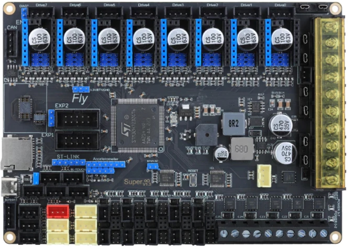
The Fly-Super8Pro by Mellow is a high-performance flight controller designed for advanced drone applications. It offers multiple input/output options, integrated sensors, and support for various communication protocols, making it an ideal choice for both hobbyists and professional drone developers.
Explore Projects Built with Fly-Super8Pro
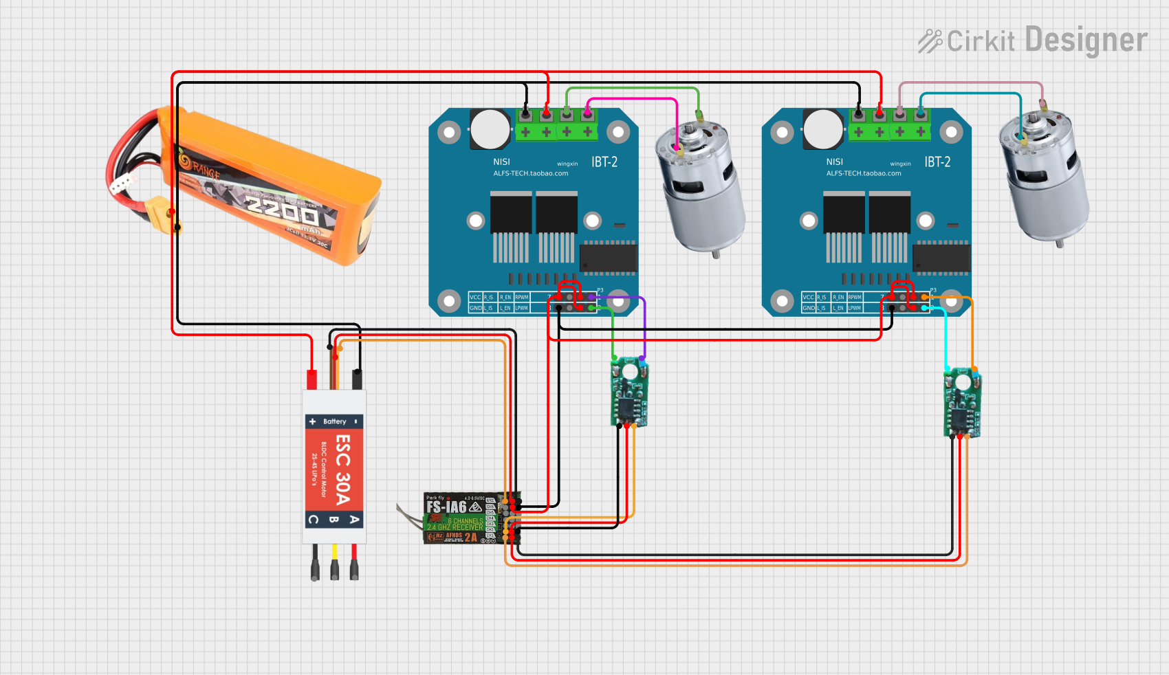
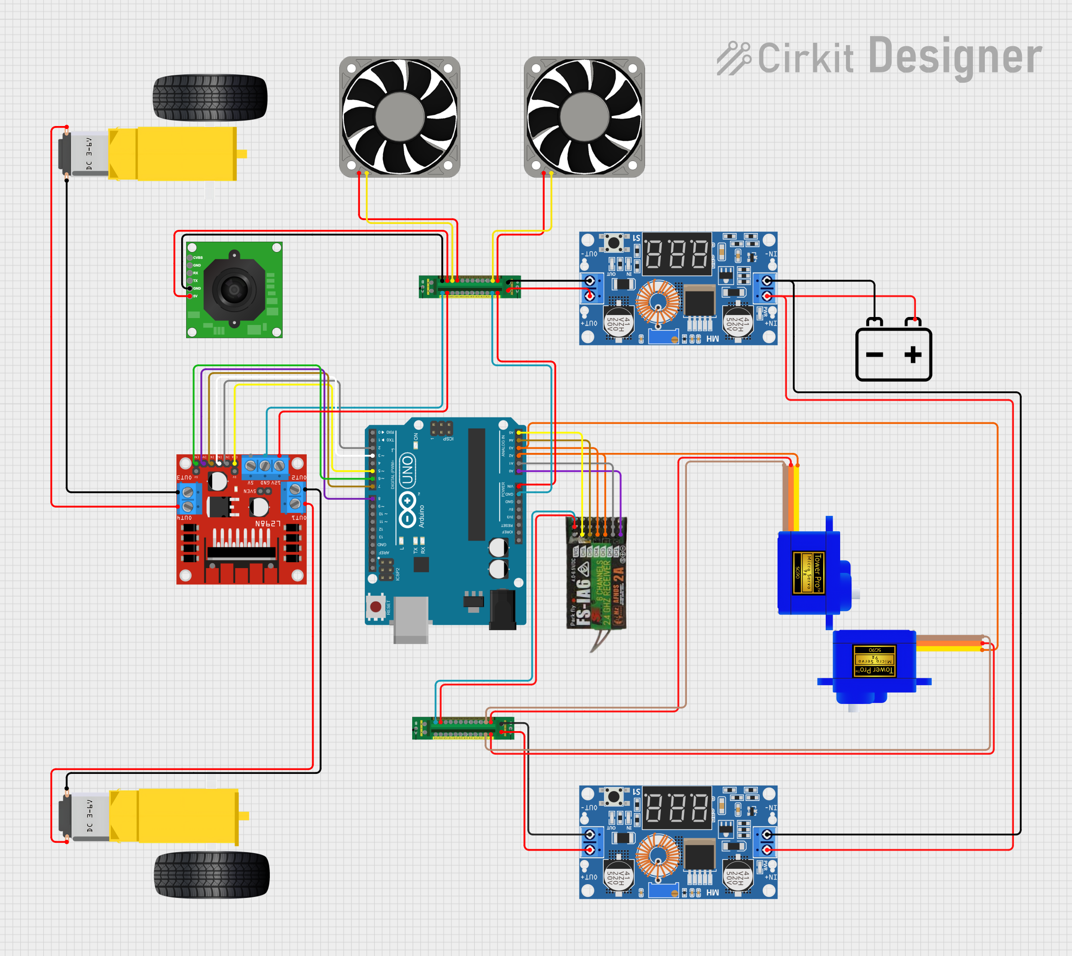
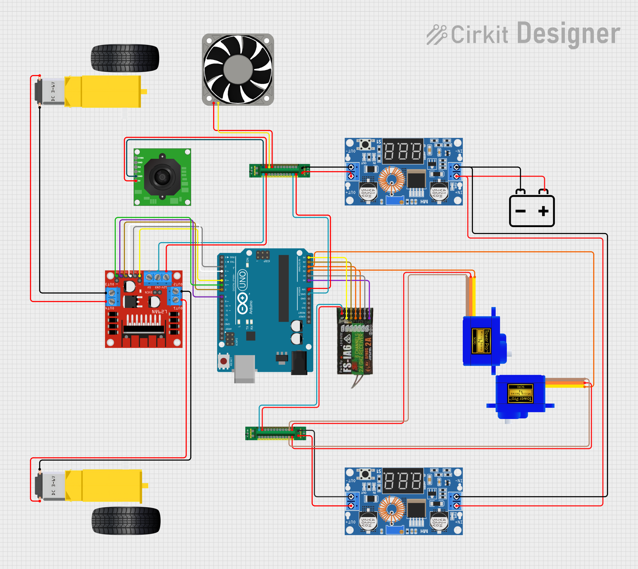
Explore Projects Built with Fly-Super8Pro
Common Applications and Use Cases
- Aerial Photography and Videography: Provides stable flight control for capturing high-quality images and videos.
- Racing Drones: Offers precise control and high-speed performance for competitive drone racing.
- Research and Development: Suitable for academic and commercial research projects involving autonomous flight and advanced drone functionalities.
- Agricultural Drones: Can be used in drones for crop monitoring, spraying, and other agricultural applications.
Technical Specifications
Key Technical Details
| Specification | Value |
|---|---|
| Input Voltage | 5V - 12V |
| Current Consumption | 500mA @ 5V |
| Processor | STM32F765 |
| IMU Sensors | MPU6000 (Gyro/Accelerometer), ICM20602 |
| Barometer | BMP280 |
| Flash Memory | 16MB |
| UART Ports | 6 |
| I2C Ports | 2 |
| CAN Bus | 1 |
| PWM Outputs | 8 |
| Dimensions | 36mm x 36mm |
| Weight | 12g |
Pin Configuration and Descriptions
| Pin Number | Pin Name | Description |
|---|---|---|
| 1 | GND | Ground |
| 2 | 5V | 5V Power Input |
| 3 | UART1_TX | UART1 Transmit |
| 4 | UART1_RX | UART1 Receive |
| 5 | UART2_TX | UART2 Transmit |
| 6 | UART2_RX | UART2 Receive |
| 7 | I2C_SCL | I2C Clock Line |
| 8 | I2C_SDA | I2C Data Line |
| 9 | CAN_H | CAN Bus High |
| 10 | CAN_L | CAN Bus Low |
| 11 | PWM1 | PWM Output 1 |
| 12 | PWM2 | PWM Output 2 |
| 13 | PWM3 | PWM Output 3 |
| 14 | PWM4 | PWM Output 4 |
| 15 | PWM5 | PWM Output 5 |
| 16 | PWM6 | PWM Output 6 |
| 17 | PWM7 | PWM Output 7 |
| 18 | PWM8 | PWM Output 8 |
Usage Instructions
How to Use the Component in a Circuit
Power Supply:
- Connect the 5V power input to a stable 5V power source.
- Ensure the ground (GND) is connected to the common ground of the circuit.
Connecting Sensors:
- Use the I2C ports (SCL and SDA) to connect external sensors.
- Ensure proper pull-up resistors are used if required by the sensors.
Communication:
- Use the UART ports for serial communication with other devices such as GPS modules, telemetry radios, or other microcontrollers.
- The CAN bus can be used for communication with other CAN-enabled devices.
PWM Outputs:
- Connect the PWM outputs to the Electronic Speed Controllers (ESCs) of the drone motors.
- Ensure the correct mapping of PWM outputs to the respective motors.
Important Considerations and Best Practices
- Power Supply: Ensure a stable and clean power supply to avoid noise and potential damage to the board.
- Heat Management: The board may generate heat during operation. Ensure proper ventilation or cooling mechanisms are in place.
- Firmware Updates: Regularly check for firmware updates from the manufacturer to ensure optimal performance and new features.
- Calibration: Calibrate the IMU sensors and barometer before the first flight and periodically thereafter to maintain accuracy.
Troubleshooting and FAQs
Common Issues and Solutions
Board Not Powering On:
- Solution: Check the power supply connections and ensure the voltage is within the specified range (5V - 12V).
Unstable Flight:
- Solution: Recalibrate the IMU sensors and check for any loose connections or damaged components.
No Communication via UART:
- Solution: Verify the baud rate settings and ensure the correct UART ports are being used.
PWM Outputs Not Working:
- Solution: Check the connections to the ESCs and ensure the correct PWM mapping in the flight control software.
FAQs
Q1: Can the Fly-Super8Pro be used with an Arduino UNO?
- A1: Yes, the Fly-Super8Pro can be interfaced with an Arduino UNO using the UART or I2C communication protocols.
Q2: How do I update the firmware on the Fly-Super8Pro?
- A2: Firmware updates can be performed using the manufacturer's software tool. Follow the instructions provided by Mellow for the update process.
Q3: What is the maximum range of the CAN bus?
- A3: The maximum range of the CAN bus depends on the baud rate and the quality of the cabling. Typically, it can range from a few meters to several hundred meters.
Q4: Can I use the Fly-Super8Pro for autonomous flight?
- A4: Yes, the Fly-Super8Pro supports autonomous flight features. Ensure you have the necessary sensors and software configured for autonomous operations.
Example Code for Arduino UNO
#include <Wire.h>

// I2C address of the Fly-Super8Pro
#define FLY_SUPER8PRO_ADDR 0x68

void setup() {
  // Initialize I2C communication
  Wire.begin();
  Serial.begin(9600);

  // Check communication with Fly-Super8Pro
  Wire.beginTransmission(FLY_SUPER8PRO_ADDR);
  if (Wire.endTransmission() == 0) {
    Serial.println("Fly-Super8Pro connected successfully.");
  } else {
    Serial.println("Failed to connect to Fly-Super8Pro.");
  }
}

void loop() {
  // Request data from Fly-Super8Pro
  Wire.beginTransmission(FLY_SUPER8PRO_ADDR);
  Wire.write(0x00); // Register to read from
  Wire.endTransmission();

  Wire.requestFrom(FLY_SUPER8PRO_ADDR, 6); // Request 6 bytes of data

  if (Wire.available() == 6) {
    int16_t ax = Wire.read() << 8 | Wire.read();
    int16_t ay = Wire.read() << 8 | Wire.read();
    int16_t az = Wire.read() << 8 | Wire.read();

    Serial.print("Accel X: "); Serial.print(ax);
    Serial.print(" Y: "); Serial.print(ay);
    Serial.print(" Z: "); Serial.println(az);
  }

  delay(1000); // Wait for 1 second before next read
}
This example code demonstrates how to establish I2C communication between an Arduino UNO and the Fly-Super8Pro to read accelerometer data. Ensure the Fly-Super8Pro is properly connected to the Arduino's I2C pins (SDA to A4, SCL to A5) and powered correctly.
By following this documentation, users can effectively integrate and utilize the Fly-Super8Pro in their drone projects, ensuring optimal performance and reliability.