How to Use ESP32-CAM Module : Examples, Pinouts, and Specs
Introduction
The ESP32-CAM Module, manufactured by Espressif Systems (Part ID: OV2640), is a low-cost development board that combines the powerful ESP32 chip with integrated Wi-Fi and Bluetooth capabilities. It also features a camera module, making it ideal for image capture, video streaming, and IoT applications. This compact module is widely used in projects requiring wireless connectivity and visual data processing.
Explore Projects Built with ESP32-CAM Module


Explore Projects Built with ESP32-CAM Module
Common Applications and Use Cases
- Wireless video surveillance systems
- Smart home devices (e.g., doorbell cameras, baby monitors)
- IoT projects with image recognition or streaming
- Remote monitoring and control systems
- Robotics and AI-based vision systems
Technical Specifications
The ESP32-CAM Module is designed to deliver high performance in a compact form factor. Below are its key technical specifications:
General Specifications
| Parameter | Value |
|---|---|
| Microcontroller | ESP32-D0WDQ6 |
| Wireless Connectivity | Wi-Fi 802.11 b/g/n, Bluetooth 4.2 |
| Camera Sensor | OV2640 |
| Flash Memory | 4 MB (PSRAM) |
| Operating Voltage | 3.3V |
| Power Supply Range | 5V (via external power source) |
| Dimensions | 27mm x 40.5mm |
Camera Specifications
| Parameter | Value |
|---|---|
| Resolution | Up to 1600x1200 (UXGA) |
| Image Format | JPEG, BMP, GRAYSCALE |
| Lens Type | Fixed Focus |
| Field of View (FOV) | 66.5° |
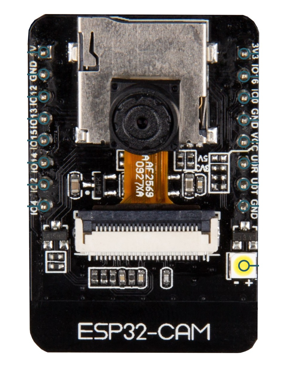
Pin Configuration and Descriptions
The ESP32-CAM Module has a total of 16 pins. Below is the pinout and description:
| Pin Name | Pin Number | Description |
|---|---|---|
| GND | 1 | Ground |
| 3.3V | 2 | 3.3V Power Supply |
| 5V | 3 | 5V Power Supply |
| U0R | 4 | UART0 Receive (RX) |
| U0T | 5 | UART0 Transmit (TX) |
| GPIO0 | 6 | GPIO Pin 0 (used for boot mode selection) |
| GPIO1 | 7 | GPIO Pin 1 |
| GPIO2 | 8 | GPIO Pin 2 |
| GPIO3 | 9 | GPIO Pin 3 |
| GPIO4 | 10 | GPIO Pin 4 |
| GPIO12 | 11 | GPIO Pin 12 (used for SD card data) |
| GPIO13 | 12 | GPIO Pin 13 (used for SD card data) |
| GPIO14 | 13 | GPIO Pin 14 (used for SD card clock) |
| GPIO15 | 14 | GPIO Pin 15 (used for SD card command) |
| GPIO16 | 15 | GPIO Pin 16 |
| RESET | 16 | Reset Pin |
Usage Instructions
The ESP32-CAM Module is versatile and can be used in a variety of projects. Below are the steps to get started:
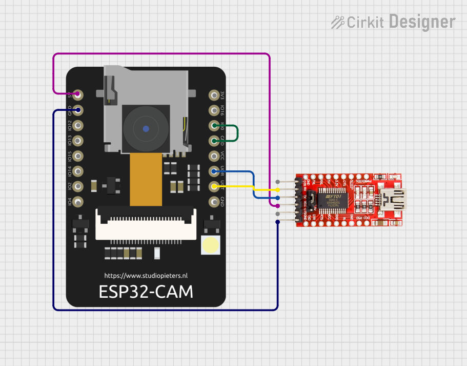
Connecting the ESP32-CAM to a Circuit
- Power Supply: Connect the 5V pin to a 5V power source and GND to ground. Ensure the power supply can provide at least 500mA.
- Programming Mode: To upload code, connect GPIO0 to GND and reset the module. This puts the ESP32-CAM in programming mode.
- UART Communication: Use a USB-to-TTL converter to connect the U0R (RX) and U0T (TX) pins to your computer for programming.
- Camera: The OV2640 camera module is pre-attached. Ensure it is securely connected to the board.
Important Considerations
- Power Requirements: The ESP32-CAM requires a stable 5V power supply. Insufficient power can cause instability.
- Heat Management: The module may heat up during operation. Ensure proper ventilation.
- Antenna: For better Wi-Fi performance, use an external antenna if needed.
Example Code for Arduino UNO
Below is an example of how to use the ESP32-CAM with the Arduino IDE to capture and stream video:
#include <WiFi.h>
#include <esp_camera.h>

// Replace with your Wi-Fi credentials
const char* ssid = "Your_SSID";
const char* password = "Your_PASSWORD";

void startCameraServer();

void setup() {
  Serial.begin(115200);
  Serial.println();

  // Connect to Wi-Fi
  WiFi.begin(ssid, password);
  while (WiFi.status() != WL_CONNECTED) {
    delay(500);
    Serial.print(".");
  }
  Serial.println("");
  Serial.println("WiFi connected");
  Serial.println("IP address: ");
  Serial.println(WiFi.localIP());

  // Initialize the camera
  camera_config_t config;
  config.ledc_channel = LEDC_CHANNEL_0;
  config.ledc_timer = LEDC_TIMER_0;
  config.pin_d0 = 5;
  config.pin_d1 = 18;
  config.pin_d2 = 19;
  config.pin_d3 = 21;
  config.pin_d4 = 36;
  config.pin_d5 = 39;
  config.pin_d6 = 34;
  config.pin_d7 = 35;
  config.pin_xclk = 0;
  config.pin_pclk = 22;
  config.pin_vsync = 25;
  config.pin_href = 23;
  config.pin_sscb_sda = 26;
  config.pin_sscb_scl = 27;
  config.pin_pwdn = -1;
  config.pin_reset = -1;
  config.xclk_freq_hz = 20000000;
  config.pixel_format = PIXFORMAT_JPEG;

  // Initialize the camera
  if (!esp_camera_init(&config)) {
    Serial.println("Camera initialized successfully");
  } else {
    Serial.println("Camera initialization failed");
    return;
  }

  // Start the camera server
  startCameraServer();
}

void loop() {
  // Main loop does nothing; camera server handles requests
}
Notes:
- Install the ESP32 board package in the Arduino IDE before uploading the code.
- Replace
Your_SSIDandYour_PASSWORDwith your Wi-Fi credentials.
Troubleshooting and FAQs
Common Issues
Module Not Detected by Computer:
- Ensure the USB-to-TTL converter is properly connected.
- Check that GPIO0 is connected to GND during programming.
Camera Initialization Failed:
- Verify that the camera module is securely connected.
- Ensure the power supply is stable and sufficient.
Wi-Fi Connection Issues:
- Double-check the SSID and password in the code.
- Ensure the Wi-Fi signal is strong.
Overheating:
- Provide adequate ventilation or use a heatsink if necessary.
FAQs
Q: Can I use the ESP32-CAM without an external antenna?
A: Yes, the module has a built-in PCB antenna, but an external antenna can improve performance.
Q: What is the maximum resolution of the camera?
A: The OV2640 camera supports up to 1600x1200 (UXGA) resolution.
Q: Can I use the ESP32-CAM for face recognition?
A: Yes, the ESP32-CAM supports face detection and recognition with appropriate libraries.
Q: How do I reset the module?
A: Use the RESET pin or press the onboard reset button.
By following this documentation, you can effectively use the ESP32-CAM Module in your projects.