How to Use RS422 to TTL Converter: Examples, Pinouts, and Specs
Introduction
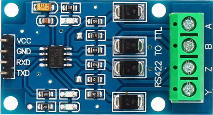
The RS422 to TTL Converter by Elecbee is a compact and reliable device designed to bridge the gap between RS422 differential signals and TTL (Transistor-Transistor Logic) levels. This converter enables seamless communication between devices that operate on different voltage levels, making it an essential component in industrial automation, embedded systems, and data communication applications.
Explore Projects Built with RS422 to TTL Converter


Explore Projects Built with RS422 to TTL Converter
Common Applications and Use Cases
- Industrial Automation: Connecting RS422-based sensors or controllers to TTL-based microcontrollers.
- Embedded Systems: Interfacing RS422 communication modules with TTL-compatible devices like Arduino or Raspberry Pi.
- Data Communication: Converting RS422 signals for use in TTL-based UART communication.
- Robotics: Enabling communication between RS422 motor controllers and TTL-based processors.
Technical Specifications
The RS422 to TTL Converter is designed to meet the needs of a wide range of applications. Below are its key technical details:
General Specifications
| Parameter | Value |
|---|---|
| Manufacturer | Elecbee |
| Input Signal Type | RS422 Differential Signal |
| Output Signal Type | TTL Logic Levels |
| Operating Voltage | 3.3V to 5V |
| Data Rate | Up to 10 Mbps |
| Operating Temperature | -40°C to 85°C |
| Dimensions | 25mm x 15mm x 5mm |
Pin Configuration and Descriptions
| Pin Name | Type | Description |
|---|---|---|
| VCC | Power Input | Connect to 3.3V or 5V power supply. |
| GND | Ground | Connect to the ground of the power supply. |
| A (RS422+) | Input | Positive RS422 differential input signal. |
| B (RS422-) | Input | Negative RS422 differential input signal. |
| TXD | Output | TTL-level transmit data output. |
| RXD | Input | TTL-level receive data input. |
Usage Instructions
How to Use the RS422 to TTL Converter in a Circuit
- Power the Converter: Connect the
VCCpin to a 3.3V or 5V power source and theGNDpin to the ground. - Connect RS422 Signals: Attach the RS422 differential signal lines to the
A(RS422+) andB(RS422-) pins. - Connect TTL Signals:
- For transmitting data, connect the
TXDpin to the RX pin of your TTL-compatible device (e.g., microcontroller). - For receiving data, connect the
RXDpin to the TX pin of your TTL-compatible device.
- For transmitting data, connect the
- Verify Connections: Double-check all connections to ensure proper signal flow and avoid damage to the converter or connected devices.
- Test Communication: Power on the system and test data transmission between the RS422 and TTL devices.
Important Considerations and Best Practices
- Voltage Compatibility: Ensure the TTL device operates at the same voltage level (3.3V or 5V) as the converter.
- Signal Termination: For long RS422 communication lines, use proper termination resistors (typically 120Ω) to minimize signal reflections.
- Data Rate: Verify that the data rate of the RS422 device does not exceed the 10 Mbps limit of the converter.
- Noise Reduction: Use shielded cables for RS422 connections in noisy environments to improve signal integrity.
Example: Connecting to an Arduino UNO
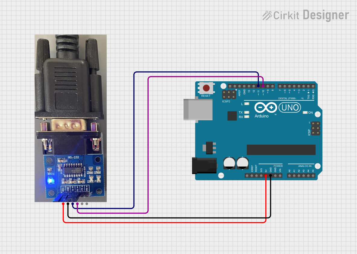
Below is an example of how to connect the RS422 to TTL Converter to an Arduino UNO and use it to receive data:
Circuit Diagram
VCC→ 5V pin on ArduinoGND→ GND pin on ArduinoTXD→ Pin 10 on Arduino (RX)RXD→ Pin 11 on Arduino (TX)AandB→ RS422 differential signal lines
Arduino Code
// Example code for using RS422 to TTL Converter with Arduino UNO
// This code reads data from the RS422 device and prints it to the Serial Monitor.

#include <SoftwareSerial.h>

// Define RX and TX pins for SoftwareSerial
#define RX_PIN 10  // Connect to TXD pin of the converter
#define TX_PIN 11  // Connect to RXD pin of the converter

// Initialize SoftwareSerial object
SoftwareSerial rs422Serial(RX_PIN, TX_PIN);

void setup() {
  // Start the hardware serial communication (for Serial Monitor)
  Serial.begin(9600);
  // Start the RS422 serial communication
  rs422Serial.begin(9600);

  Serial.println("RS422 to TTL Converter Test");
}

void loop() {
  // Check if data is available from the RS422 device
  if (rs422Serial.available()) {
    // Read the incoming data
    char incomingData = rs422Serial.read();
    // Print the data to the Serial Monitor
    Serial.print("Received: ");
    Serial.println(incomingData);
  }

  // Optional: Send data to the RS422 device
  if (Serial.available()) {
    char outgoingData = Serial.read();
    rs422Serial.write(outgoingData);
  }
}
Troubleshooting and FAQs
Common Issues and Solutions
No Data Transmission
- Cause: Incorrect wiring or loose connections.
- Solution: Verify all connections, especially the
A,B,TXD, andRXDpins.
Data Corruption
- Cause: Signal noise or improper termination.
- Solution: Use shielded cables and add 120Ω termination resistors at both ends of the RS422 line.
Device Not Powering On
- Cause: Incorrect power supply voltage.
- Solution: Ensure the
VCCpin is connected to a 3.3V or 5V power source.
Slow Data Rate
- Cause: Mismatch between RS422 device and converter data rates.
- Solution: Configure both devices to use the same baud rate.
FAQs
Q: Can this converter work with RS485 signals?
A: No, this converter is specifically designed for RS422 signals. RS485 requires a different protocol and hardware.Q: What is the maximum cable length for RS422 communication?
A: RS422 supports cable lengths up to 1200 meters, but performance may vary depending on the data rate and cable quality.Q: Can I use this converter with a 3.3V TTL device?
A: Yes, the converter supports both 3.3V and 5V TTL logic levels. Ensure theVCCpin matches the voltage level of your TTL device.Q: Is the converter bidirectional?
A: Yes, it supports bidirectional communication for both transmitting and receiving data.
This documentation provides all the necessary details to effectively use the Elecbee RS422 to TTL Converter in your projects.